EasyManua.ls Logo

SoundCraft SPIRIT LIVE 4 2 User Manual

SoundCraft SPIRIT LIVE 4 2
44 pages
To Next Page IconTo Next Page
Page #1 background imageLoading...
Page #1 background image
24
25
26
1 GRP 2
3 GRP 4
LMIXL MIX R
Part No: ZM0111
USERS GUIDEUSERS GUIDEUSERS GUIDEUSERS GUIDE
Warranty .........................3
Introduction .......................4
Basic Principles of PA Mixing .............5
Installation & Safety Precautions ...........7
Sicherheitshinweise ...............9
Precautions ...................10
Sicurezza ....................11
Precauciones de Seguridad ..........12
Connecting It Up....................13
Wiring It Up ......................14
Getting to Know Your Console ............18
Mono Inputs ...................18
Stereo Inputs ..................21
Group Section..................23
Master Section .................24
Using Your Spirit Live 4 Console ..........26
Applications ......................28
Care Of Your Mixer ..................34
Glossary ........................34
Typical Specifications.................36
Dimensions ......................37
System Block Diagram ................38
Panel Layout ......................39
Mark-up Sheets ....................40
Typical Connecting Leads ..............42
2
For further details contact:
Harman International Industries Ltd.
Cranborne House, Cranborne Road
Potters Bar, Hertfordshire, EN6 3JN, UK
Tel: +44 (0) 1707 665000
Fax: +44 (0) 1707 660742
e-mail: info@soundcraft.com
www.soundcraft.com
A Harman International Company
CONTENTS
Question and Answer IconNeed help?

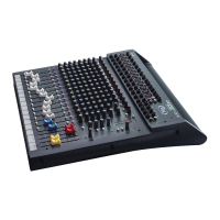
Do you have a question about the SoundCraft SPIRIT LIVE 4 2 and is the answer not in the manual?

SoundCraft SPIRIT LIVE 4 2 Specifications

General IconGeneral
BrandSoundCraft
ModelSPIRIT LIVE 4 2
CategoryMusic Mixer
LanguageEnglish

Summary

Warranty

Introduction

Basic Principles of PA Mixing

The Mixer

Explains the fundamental purpose and operation of a mixer.

Equaliser Controls

Details the flexible and precise control of frequency response using EQ.

Auxiliary Sends

Describes routing signals to secondary outputs for foldback or effects.

Pan Control

Explains adjusting the signal's position within the stereo mix.

Pre-Fade-Listen (PFL)

Details monitoring signals at specific points without affecting the main mix.

Insert 'A' Gauge Jack Socket

Explains the use of insert points for external signal processing.

Installation and Safety Precautions

Installing the Mixer

Guidance on correct connection, positioning, and cabling for mixer operation.

Safety Precautions

Essential safety guidelines to prevent injury and equipment damage.

Connecting It Up

Wiring It Up

MIC INPUT

Details on connecting microphones to the mixer's XLR input.

LINE INPUT

Instructions for connecting line-level sources via jack sockets.

INSERT POINT

Explanation of the unbalanced insert point for signal processing.

Outputs

Stereo Inputs and Cass/CD Inputs

Details on connecting stereo sources and CD/cassette players.

Stereo Returns

Explains connecting effects units or external sources to stereo returns.

Mix and Group Inserts

Describes insert points for Mix and Group outputs for signal processing.

Mix, Group & Matrix Wiring

Wiring for Mix, Group, and Matrix outputs using XLR connectors.

Headphone Wiring

Wiring for the stereo headphone output.

Fault Finding Guide

Getting to Know Your Console

Mono Input Channel

Details the XLR and 3-pole jack inputs for mono channels.

+48V Phantom Power

Explains the +48V phantom power switch for condenser mics.

Phase Switch

Describes the phase reversal switch for input signals.

Input Sensitivity Adjustment

How to set the input gain to avoid distortion or noise.

Stereo Inputs

Cass/CD Input Section

Input section for cassette or CD players, with gain sensitivity settings.

Stereo Input Gain

Setting input gain for various professional and semi-professional sources.

Stereo Input Aux Sends 1 & 2

Routing input signals to auxiliary busses 1 & 2.

Stereo Input PFL

Monitoring pre-fade signals for stereo inputs.

Stereo Input Level to Mix

Setting the stereo signal level to the main stereo mix.

Main Stereo Input Section

Details on the main stereo input for full-facility channels.

Stereo Input Gain Adjustment

Matching input level for diverse audio sources.

Stereo Input Equaliser

Using HF and LF shelving controls for frequency adjustment.

Group Section

Group Faders

Faders for controlling the level of group signals.

Groups to Mix, Stereo/Mono

Routing group signals to the stereo Mix or as mono subgroups.

Matrix Sends (Groups)

Sending group signals to Matrix outputs for additional mixes.

Group PFL

Monitoring pre-fade signals for group channels.

Stereo Returns

Mixing outputs from effects or external sources via stereo returns.

Master Section

Bargraph Meters

Visual monitoring of Mix and Group output levels.

Mix Faders

Controls for setting the final level of the Mix outputs.

Matrix Sends

Controlling signal level sent to Matrix A & B buses.

Matrix Masters

Master controls for the final output level of each Matrix.

Talkback Function

Input and routing for a talkback microphone.

Power On LEDs

LED indicators for console power supply status.

Using Your Spirit Live 42 Console

Microphone Placement

Essentials of successful sound reinforcement through microphone choice and placement.

Initial Set Up

Guidance on setting initial control positions after connecting the system.

Application 1: Live Sound Reinforcement

Application 2: Live Sound with Centre Cluster

Application 3: Additional Stereo Inputs

Application 4: Theatre Sound

Application 5: Using the Mute Buses

Application 6: Linking Two Live 42 Mixers

Care of Your Mixer

General Precautions

Guidelines for maintaining the mixer's condition and longevity.

Glossary of Terms

Definitions of technical terms used in the manual.

Typical Specifications

Noise Specifications

Measured RMS noise levels for various mixer paths.

Frequency Response

Frequency range and attenuation characteristics.

Input & Output Impedances

Electrical impedance values for mixer inputs and outputs.

Input & Output Levels

Maximum signal levels for various inputs and outputs.

Dimensions

Flight Case Mounting

Information on mounting the console in a flight case.

System Block Diagram

Mark-Up Sheet

Typical Connecting Leads

Related product manuals