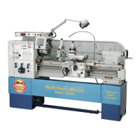
Why does the motor on my South bend SB1012 overheat?
Model | SB1012 |
---|---|
Swing Over Bed | 12 inches |
Distance Between Centers | 36 inches |
Spindle Speed Range | 70 - 1400 RPM |
Spindle Speed | Variable |
Spindle Taper | MT#4 |
Motor Power | 2 HP |
Voltage | 220V |
Overview of the lathe's history, design, and features.
Identifies potential hazards and signals used in the manual.
Outlines essential safety practices for machine operation.
Outlines the basic steps for preparing the lathe for operation.
Details environmental requirements for safe and optimal operation.
Guidelines for connecting the machine to a power source.
Specifies adequate lighting requirements for safe operation.
Considers machine, equipment, and workpiece weight for placement.
Recommends space for operator movement and auxiliary equipment.
Describes the process and tools for accurate leveling.
Specifies electrical requirements for the SB1012 model.
Specifies electrical requirements for SB1014 and SB1037 models.
Specifies electrical requirements for the SB1013 model.
Specifies electrical requirements for SB1015 and SB1038 models.
Identifies and describes the main power switch.
Explains the various controls located on the headstock.
Details the controls related to the carriage movement.
Controls the flow of cutting fluid from the nozzle.
Operates the compound slide and includes a graduated scale.
Secures the carriage for rigidity and accuracy.
Describes the function and operation of the foot brake.
Step-by-step guide for safely removing chucks and faceplates.
Guide for installing and adjusting camlock studs for proper mounting.
Steps for changing jaws on the 3-jaw chuck.
Procedure for securely mounting a workpiece in the 3-jaw chuck.
Procedure for securely mounting a workpiece in the 4-jaw chuck.
Procedure for clamping workpieces onto the faceplate.
Instructions for mounting workpieces between centers.
Steps for installing a dead center in the spindle.
Details on the use and characteristics of dead centers.
Details on the use and characteristics of live centers.
Steps to set the compound slide to a specific angle.
Moves the carriage along the bed.
Moves the cross slide toward or away from the work.
Controls the position of the cutting tool.
Factors affecting spindle speed and calculation methods.
Instructions for reversing feed direction.
Steps to engage power feed for carriage or cross slide.
Describes the gear setup for normal operations.
Describes the gear setup for modular and diametral pitch turning.
Step-by-step guide to change gear positions.
Correct position of the feed control lever for threading.
Engages carriage with leadscrew for threading.
Using the thread dial for TPI divisible by four.
Using the thread dial for TPI not divisible by four.
Using the thread dial for odd numbered TPI.
Using the thread dial for 1/2 fractional TPI.
Step-by-step instructions for adding cutting fluid.
Potential biological and poison hazards associated with cutting fluid.
Steps for preparing the machine for storage up to one year.
Steps for preparing the machine for storage over one year.
Adjusting backlash on the compound leadscrew.
Adjusting backlash on the cross slide leadscrew.
Diagnosing and fixing noisy motor operations.
Troubleshooting steps for an overheating motor.
Diagnosing causes for a loud or bogging motor during cutting.
Troubleshooting steps for achieving a good surface finish.
Resolving issues with removing tapered tools from the tailstock.
Adjusting gibs and other components for smooth feed operation.
Troubleshooting steps when handwheels are difficult to move.
Addressing excessive vibration during cutting operations.
Physical dimensions of the lathe.
Dimensions of the lathe when crated for shipping.
Electrical power source and connection requirements.
Details on the main and lubrication motors.
Lubrication type and specifications.
Key operational measurements and travel distances.
Detailed specifications about the headstock and spindle.
Specifications for the tailstock travel and taper.
Information on available thread pitches and feed rates.
Warning about the dangers of working with live electrical sources.
Emphasis on ensuring tight and secure electrical connections.
Warnings against unauthorized wiring modifications.
Requirement to follow power source connection guidelines.
Safety precautions regarding stored electrical charges.
Risks associated with damaged wires or components.
Visual identification of RPM sensor and door limit switch.
Visual identification of the brake limit switch.
Visual identification of the chuck guard limit switch.