24
Integral Air Handler Control
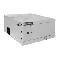
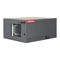
The SpacePak ESP and WCSP air handlers now feature
a sophisticated control platform that has the ability to
control fan speed by measuring static pressure and
calculating airflow (CFM), as well as heat exchanger coil
temperature.
The fan control logic can be configured to maintain a
constant static pressure, or constant fan speed, with
individual settings that can be assigned to each of five
different operating inputs; Cooling Y1, Cooling Y2,
Heating W1, Heating W2, and G fan only. Each set point
is adjusted separately through the onscreen interface,
which is an integral component of the control board.
In each mode, the fan will gradually increase to the
specific set point in order to minimize perceived airflow
and duct noise. In the Cooling and Heating modes, the
fan will not ramp up to the desired set point until the coil
reaches the appropriate temperature. Both heating and
cooling fan start set points can be adjusted through the
onscreen menu following the menu tree located in this
section.
The screen will also display the delivered airflow, in Cubic
Feet per Minute, delivered by the air handler. CFM
calculation is an approximation based upon laboratory
test conditions, and may be affected by certain system
construction features such as temperature and elevation
The primary setup criteria for all Small Duct High Velocity
systems should always be Duct Static Pressure. CFM
and static pressure displayed on screen should be used
as REFERENCE ONLY.
All delivered airflow and static pressure, for each
application, should be verified upon installation with
calibrated equipment to ensure proper system operation
and for troubleshooting purposes. For ESP models; The
control also manages output signals to the outdoor
condenser or heat pump, whether single or dual stage, as
well as indoor accessories such as an ERV/HRV,
Humidifier, Electric Heater or Auxiliary Hydronic Heating
Coil.
For WCSP models; The control also manages output
signals to the Geo or Air to Water Heat Pump, as well as
indoor accessories such as an ERV/HRV, Humidifier,
Electric Heater, Auxiliary Hydronic Heating Coil, or SSIC
Hydronic System Interface Controller.
Refer to Section 3 for more detailed description and start-
up instruction as well as the appropriate wiring diagrams
located in section 2 step 7 of this manual.
 Loading...