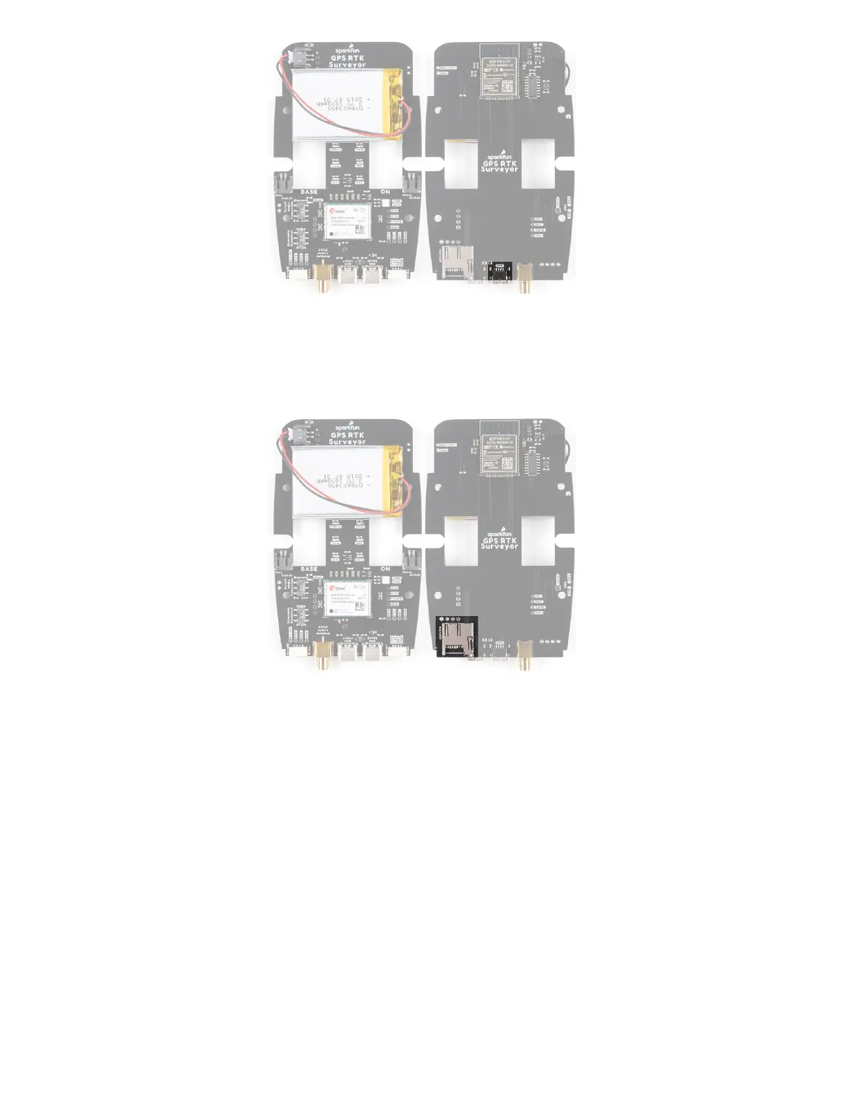
microSD
A microSD socket is situated on the ESP32 SPI bus. Any microSD up to 32GB is supported. RTK Surveyor
supports RAWX and NMEA logging to the SD card. Max logging time can also be set (default is 10 hours) to avoid
multi-gigabyte text files. For more information about RAWX and doing PPP please see this tutorial.
Hardware Assembly
The RTK Surveyor was designed to work with low-cost, off the shelf equipment. Here we’ll describe how to
assemble a Rover and Base.
Rover
Shown here is the most common RTK Rover setup. A monopole designed for cameras is used. A cell phone
holder is clamped to the monopod and the RTK Surveyor is mounted. The ¼” camera thread of the monopole is
adapted to ⅝” 11-TPI and a L1/L2 antenna is attached. A Male TNC to Male SMA cable connects the antenna to
the RTK Surveyor. No radio is needed because RTCM correction data is provided by a phone over Bluetooth.