EasyManua.ls Logo

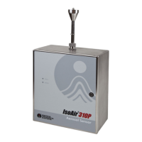
Spectris Particle Measuring Systems IsoAir 310P User Manual

Spectris Particle Measuring Systems IsoAir 310P
105 pages
To Next Page IconTo Next Page
Page #1 background imageLoading...
Page #1 background image
IsoAir® 310P
Aerosol Particle Sensor
P/N 1000016128
OPERATIONS MANUAL
Without measurement there is no control

Table of Contents

Questions and Answers:

Spectris Particle Measuring Systems IsoAir 310P Specifications

General IconGeneral
Number of Size Channels6
Light SourceLaser diode
Air InletIsokinetic sampling probe
Data StorageUp to 3, 000 samples
Flow Rate1.0 CFM (28.3 L/min)
CommunicationEthernet, USB
Power100-240 VAC, 50/60 Hz
Operating Temperature10 - 35 °C
Operating Humidity0 - 90% RH, non-condensing
Particle Size Range0.3 - 25 µm

Summary

Chapter 1 Introduction

Front Panel

Describes the status and activity LEDs on the front panel of the sensor.

Specifications

Details the technical specifications of the IsoAir 310P sensor.

Accessories

Lists standard and optional accessories for the sensor.

Options

Details available optional features like 4-20mA output and wireless.

Chapter 2 Unpacking and Installation

Unpacking the Sensor

Instructions for safely opening the shipping container and inspecting the sensor.

Sensor Installation

Guidance on planning and executing the physical installation of the sensor.

Selecting a Location

Criteria for choosing an optimal mounting location for the sensor.

Setting Up a Remote Sampling System

Instructions for configuring the sensor for remote sampling using an ISP.

Removing the Electronics Module

Step-by-step guide on how to safely remove the electronics module.

Mounting the Sensor

Instructions for securely mounting the sensor enclosure to a surface.

Connecting the Electrical Wiring

Guidelines for safely connecting the electrical wiring to the sensor.

Connecting Input-Output Cables

Information on connecting input and output cables to the sensor.

Chapter 3 Configuring for Facility Net

Before You Begin

Lists the necessary items and prerequisites for configuring the sensor.

Configuring the Sensor

Step-by-step guide to setting up the sensor's communication parameters.

Configuring Instrument Channels

Explains how to set up the sensor's data channels for different modes.

Setting the Auto-Buffer Size

Details how to configure the buffer size for sample retransmission.

Chapter 4 Facility Net Setup

Configuring the Software

Steps to configure the Facility Net software to recognize the sensor.

Reviewing Channel Configuration

How to view the particle channel thresholds configured for the sensor.

Configuring Analog Sensors

Instructions for setting up analog inputs for external sensors.

Configuring Analog Input (Optional)

Detailed guide on configuring analog inputs and calculating scale/offset.

Configuring Run-Time Settings

How to adjust instrument parameters and view status in real-time.

Chapter 5 4-20 mA Output Option

Configuring 4-20 mA Output

Details how to wire and configure the 4-20 mA output channels.

4-20 mA Out Status Channel (Optional)

Explains the status output settings and their meanings.

Particle Channel Scale Considerations

Guidance on setting scale factors for particle channels.

Chapter 6 4-20 mA Input and Solid State Outputs

4-20 mA Input

Information on connecting and using 4-20 mA analog inputs.

Solid State Outputs

How solid state outputs are slaved to LED status operations.

Analog Inputs: Connections and Configuration

Details on connecting and configuring analog inputs for current or voltage sensors.

Chapter 7 Operations

Pump Flow Alarm and Shut-off

Explains the pump flow monitoring, alarms, and automatic shut-off features.

Detector Board

Information about the detector board's operation and failure alarms.

Chapter 8 Maintenance

Sterilization of Cleanroom

Guidelines for cleaning and sterilizing the sensor enclosure.

Calibration, Service, and Shipping

Core maintenance topics including calibration, service, and shipping.

Chapter 9 Troubleshooting

Troubleshooting

Provides a table of common problems, symptoms, causes, and solutions.

Appendix A International Precautions

WARNING

General warnings about laser product compliance and potential radiation exposure.

Hazard Symbols

Explains the meaning of hazard symbols on the equipment.

Appendix B Serial Commands

Serial Commands

Lists and explains serial commands for instrument control and status.

Appendix C Wi-Fi Configuration

Router Configuration

Guidance on configuring the wireless router for sensor communication.

Steps for IsoAir 310P Wi-Fi Configuration

Step-by-step instructions for setting up Wi-Fi mode on the sensor.

Configure the Wi-Fi bridge

Instructions for configuring the Wi-Fi bridge hardware for network connectivity.

Hardware Details

Describes the physical Wi-Fi option hardware and its components.

Status LEDs

Explains the meaning of the status LEDs on the Wi-Fi bridge for diagnostics.

Tips

Provides setup tips, troubleshooting, and advice for reliable wireless networking.

Appendix D Modbus

Modbus Overview

Provides a general overview of Modbus communication and its sections.

Input Registers

Details the input registers used for configuration and data collection.

Holding Registers

Explains the holding registers for device configuration parameters.

Coils

Describes the coils used for controlling device functions and status.

Data Packet Processing

Explains how real-time and queued data packets are handled.

Appendix E OPC Configuration and Operation

IsoAir 310P OPC Identification Data

Provides Class ID, Program ID, and Description for the OPC server.

IsoAir 310P Data Access Tags

Lists and describes the data tags available via OPC for monitoring.

OPC Setup

Explains how to set up and configure the OPC server for data access.

OPC Server

Details the basic setup and connection requirements for the OPC server.

Related product manuals