Page 14 For technical questions, please call 1-888-866-5797. Item 59508
SAFETY OPERATION MAINTENANCEINSTALLATION
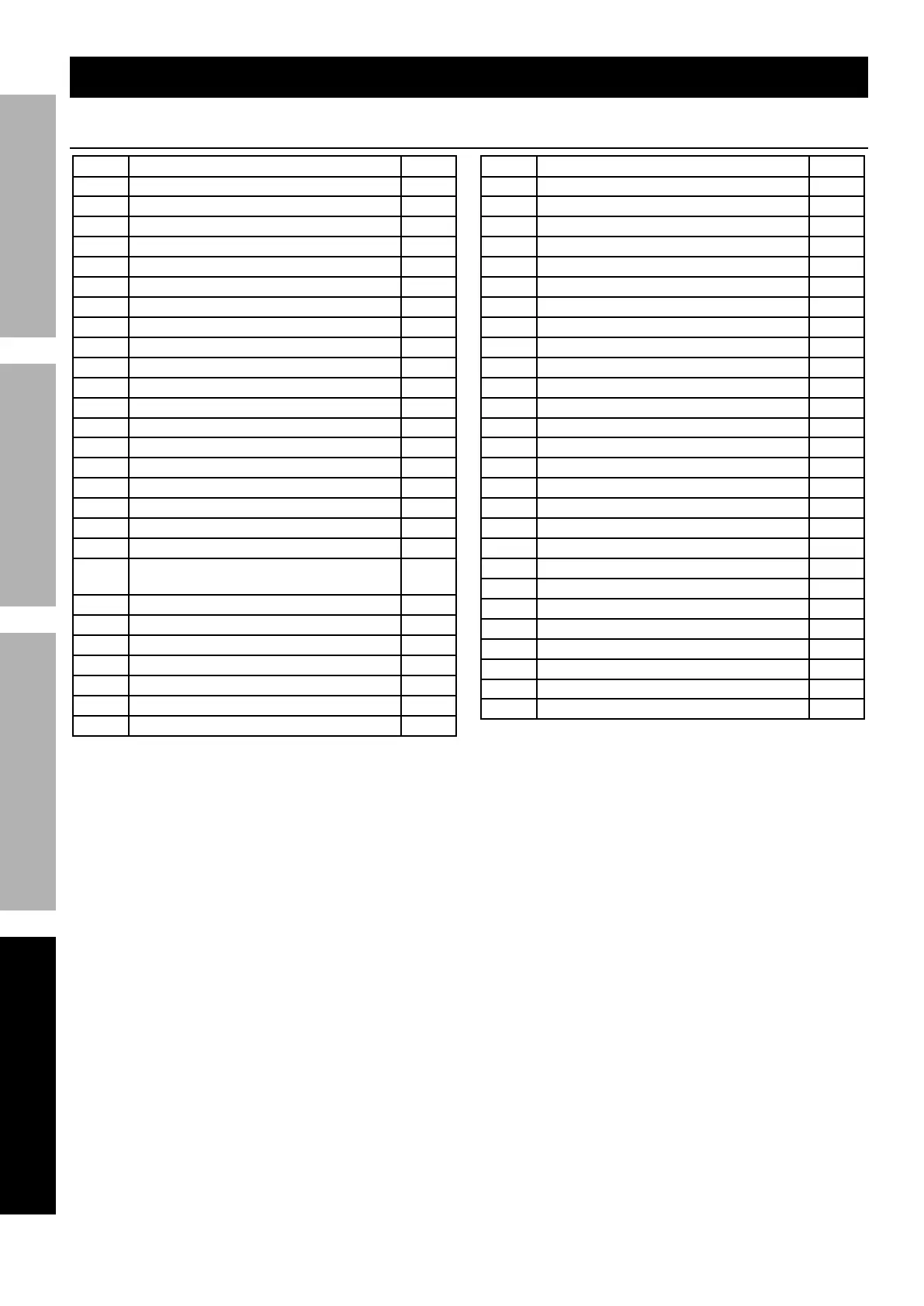
Parts Lists and Diagrams
Compressor Parts List
Part Description Qty
1 Handle 1
2 Screw, Washer and Nut 2
3 Airbrush Holder 2
4 Power Switch 1
5 Cover 1
6 Safety Valve 1
7 Pressure Switch 1
8 Flex Hose Assembly 2
9 Air Tank 1
10 Check Valve Assembly 1
11 Elbow Fitting Assembly 1
12 Drain Valve 1
13 Flex Hose 1
14 Screw 6
15 Base 1
16 Foot 4
17 Screw, Washer and Nut 4
18 Rubber Pad 8
19 Bracket 2
20 Regulator, Pressure Gage
and Moisture Filter
2
21 O-Ring 2
22 Cylinder 2
23 Screw 2
24 Valve Plate 2
25 Screw 2
26 Block 2
27 Compression Ring 2
Part Description Qty
28 Connecting Rod 2
29 Bearing 2
30 Clip 2
31 Counterweight 2
32 Protective Shield 2
33 Front Cover 1
34 Power Cord 1
35 Screw 8
36 Cylinder Head 2
37 Bolt 1
38 Screw and Washer 8
39 Pipe 1
40 Return Valve Assembly 1
41 Three Way Connector Assembly 1
42 O-Ring 2
43 Solenoid Valve 1
44 Valve Cover 2
45 Screw and Washer 4
46 Crank Case 2
47 Screw, Washer and Nut 4
48 Shock Pad 4
49 Bearing 2
50 Stator Winding 1
51 Rotary Winding 1
52 Capacitor 1
53 Rear Cover 1
54 Muffler 2
 Loading...