General Safety Information
Lockout valves are utilized in a variety of air
system applications. Because lockout valves
and other components (compressor, spray
gun, filter, regulator, lubricator, hoses, etc.)
make up a high pressure pumping system,
the following safety precautions should be
observed at all times.
1. Read the instruction manuals for each
component carefully before attempting to
assemble, disassemble, or operate your
particular system.
2. Do not exceed the pressure rating of any
component in the system.
3. Protect material lines and air lines from
damage or puncture.
4. Never point a spray gun at oneself or any
other person. Accidental discharge may
result in serious injury.
5. Check hoses for weak or worn condition
before each use, making certain that all
connections are secure.
6. Release all pressures within the system
before attempting to service any
component.
Materials
Body: Zinc
Spool: Aluminum
Detent Spring: Stainless steel
Elastomers: Nitrile
Installation
1. Shut OFF air pressure. Install valve in air
line at any angle.with air flow in direction
of arrow on body. Do not install valve
with unprotected exhaust port facing
upward.
2. Connect piping to proper ports using pipe
thread sealant on male threads only. Do
not allow sealant to enter interior of
valve.
Operation (See Figure 2)
1. When the T-handle is closed (completely
pushed in) air flow is blocked and
downstream air is exhausted. When the T-
handle is opened (completely pulled out)
air flows thru the valve to the
downstream system. The spool can be
padlocked in the closed position only. A
customer supplied padlock with a
maximum shackle diameter of 5/16" can
be used to lock the spool in the closed
position.
Disassembly (See Figure 2)
1. Valve can be disassembled without
removal from air line.
2. Shut OFF inlet pressure. Reduce pressure
in inlet and outlet lines to zero.
3. Disassemble in general accordance with
the item numbers on Figure 2. Drive pin
(Ref No. 5) out of T-handle, then remove
T-handle. Detent spring (Ref. No. 10) will
remain in groove in top of body. Pull
spool (Ref. No 7) out of body.
Cleaning (See Figure 2)
1. Clean all parts with warm water and soap.
2. Rinse and dry parts.
3. Inspect parts. Replace those found to be
damaged.
Assembly (See Figure 2)
1. Lubricate o-rings and detent spring with
o-ring grease.
2. Assemble filter as shown on Figure 2.
Make sure spring detent (Ref. No. 10) is
centered in body before installing spool
(Ref. No. 7).
3. Test valve for proper operation prior to
returning to service.
Torque Table
Ref. No. Inch Pounds (N-m)
2 (Screw) 150 (16.9)
Model ABC
4ZL03 1.87 (48) 9.72 (247) 3.47 (88)
4ZL04 1.87 (48) 9.72 (247) 3.47 (88)
4ZL05 1.87 (48) 9.72 (247) 3.47 (88)
4ZL06 2.26 (57) 12.27 (312) 4.45 (113)
Model DEF
4ZL03 7.15 (182) 4.00 (102) 2.00 (51)
4ZL04 7.15 (182) 4.00 (102) 2.00 (51)
4ZL05 7.15 (182) 4.00 (102) 2.00 (51)
4ZL06 8.82 (224) 5.00 (127) 2.50 (64)
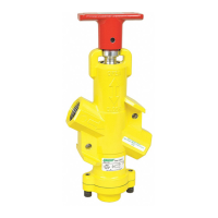
Speedaire
®
Lockout Valve
Refer to Form 5S6040 for General Safety Information and Warranty
Operating Instructions & Parts Manual 4ZL03, 4ZL04, 4ZL05, 4ZL06
Please read and save these instructions. Read carefully before attempting to assemble, install, operate or maintain the product described. Protect yourself and
others by observing all safety information. Failure to comply with instructions could result in personal injury and/or property damage! Retain instructions for
future reference.
Form 5S6086
®
E
N
G
L
I
S
H
E
S
P
A
Ñ
O
L
F
R
A
N
Ç
A
I
S
Printed in U.S.A.
06530
0708/256/VCPVP
Description
Speedaire lockout valves are manually operated, 3 port/2 position valves that block inlet air
flow and exhaust downstream air in the closed position. They can be locked only in the
closed position with a customer supplied padlock, helping to conform to OSHA Lockout
Regulations.
4ZL03 300 psi 175°F 6.6 6.6 3/8" 3/4" 2.6
4ZL04 300 175 9.3 7.9 1/2 3/4 1.6
4ZL05 300 175 12.6 8.6 3/4 3/4 1.5
4ZL06 300 175 16.2 9.2 113.3
Maximum Cv Factor
Inlet Maximum In to Out Out to Exhaust Main Exhaust Weight
Model Pressure Temperature Ports Ports Ports Port (lbs)
Specifications
Figure 1 - Dimensions in inches (mm)