1205CX LV / 2405CX LV • power supply
6
1205CX LV / 2405CX LV • power supply
7
1205CX LV / 2405CX LV Operating Instructions
The 1205CX LV and 2405CX LV are identical in features and
operation, except that the 2405CX LV is twice as powerful. The
following instructions apply for both units. Please read these
instructions and the general instructions on page 4 for the proper
use and care of these power supplies.
Set Combine/Isolate switches for desired ratio of power to light unit(s).
See the chart on the side of the power supply and the next page for ratio
combinations that are possible with up to four light units.
Set Fast/Slow switch. Normally, you will operate the unit in fast recycle
mode. However, if you do not have adequate power in your studio, this may
cause circuit breakers in your studio to blow. In this case, use slow recycle
mode.
Connect power supply to AC outlet.
Turn Power switch on. Ready/Push to Flash indicator will illuminate,
indicating 100% recycle. The unit is now fully charged and ready to fire. Do
not immediately fire the unit on the first use or when the unit has been idle
for periods over 3 weeks. Allow several minutes for the power supply’s
capacitors to form. When the power supply has been used recently you may
fire the unit immediately.
Ready/Push to Flash button may be depressed to verify proper system
operation. The Ready/Push to Flash indicator light will periodically flicker.
This is normal and indicates the operation of the voltage regulator.
When Power is on, be sure Ready/Push to Flash indicator is illuminated
before switching Power, Combine/Isolate, or Fast/Slow controls. Do not
move these switches while the unit is recycling.
The Variable Power Control simultaneously changes power of all 3
channels. When decreasing power (rotating knob from Full to -1 stop, for
example) power to the light unit(s) will not be reduced until the 1205CX LV /
2405CX LV has been fired. Press the Push to Flash button to discharge unit.
When increasing power (rotating knob from -1 stop to Full, for example) it is
immediately increased to the light units.
Rotating the Variable Power Control does not change the output of the
model lamps. Their output is controlled by the Variable Model Lamps
Controls, one control for each power channel. Rotating the knobs
immediately adjusts the output of the model lamps. This way, model lamp
output can be matched to the light units, and lighting ratios are easily
visualized.
When disassembling the system, turn Power switch to the off position.
This flashes all light units connected to the Model 1205CX LV / 2405CX LV.
Do not push the Push to Flash switch before turning power supply off. This
will damage power supply.
Unplug power cord from outlet, then disconnect light units from power
supply.
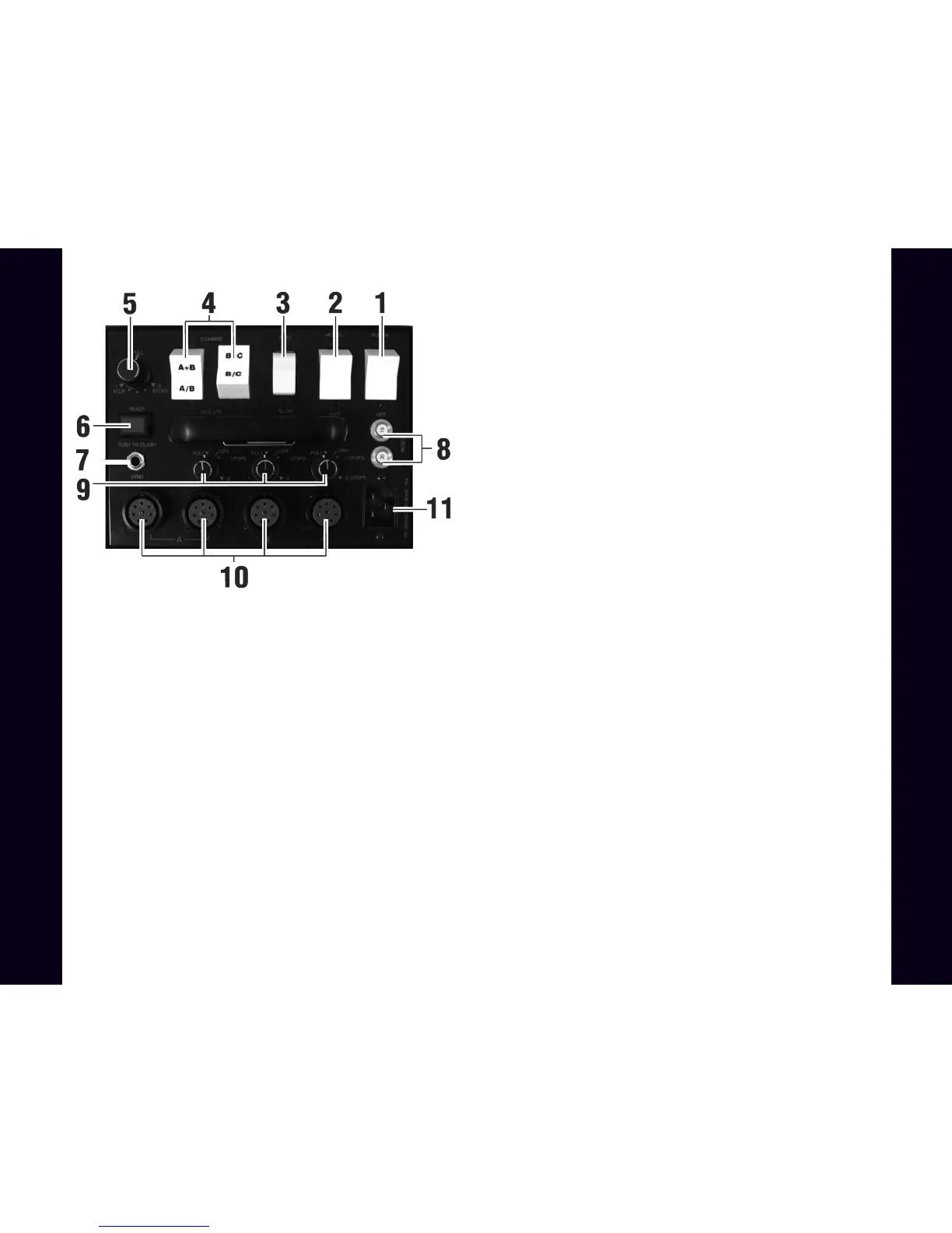
1205CX LV / 2405CX LV Description of Controls
Note:Instructions apply to all versions of 1205/2405 power supplies.
Variations in these models are in switches and AC input connector only.
1) Power — turns power supply on and off (flashes light units when turning off)
2) Model — turns model lamps on and off.
3) Fast/Slow — controls recycle rate.
4) Combine/Isolate — controls 3-channel power distribution. Combine
connects channels as indicated (A+B, B+C) with symmetrical distribution;
Isolate separates channels as indicated (A B, B C).
5) Variable Power Control — simultaneously controls power of all 3 channels,
in 1/4 stop increments, down to -2 stops (1/4 power).
6) Ready/Push to Flash — illuminates when power supply reaches 100%
recycle. Pushing the button manually triggers the flash for testing or open flash
applications.
7) Sync — socket to connect camera or slave to power supply.
8) Reset — push to reset circuit breaker. Circuit breaker disables power supply
in case of malfunction.
9) Variable Model Lamp Control (3) — controls output of model lamps, down
to -3 stops (1/8 power), independently for each channel.
10) Light Unit Outlets (4) — sockets for connecting from one to four light units
to power supply.
11) Power Input — socket for AC power cord.
 Loading...