EasyManua.ls Logo

Sperry Marine NAVIKNOT 600 SE User Manual

Sperry Marine NAVIKNOT 600 SE
138 pages
To Next Page IconTo Next Page
Page #1 background imageLoading...
Page #1 background image
Northrop Grumman Sperry Marine B.V. (Representative Office)
Woltmanstr. 19 • D-20097 • Hamburg, Germany
Tel.: +49-40-299 00-0 • Fax: +49-40-299 00-146 • E-mail: service.de@sperry.ngc.com
Operation, Installation and Service Manual
MASTER
600 SE
N.MILES
DAILY
TOTAL
kn
1234.56
123456.7
12 8. 0
0
.12
GPS QUAL.
GOOD
N AV I K N O T 6 0 0 S E
Combined Satellite and Electromagnetic Speed Log
056349/C, 18 Apr 2008

Table of Contents

Question and Answer IconNeed help?

Do you have a question about the Sperry Marine NAVIKNOT 600 SE and is the answer not in the manual?

Sperry Marine NAVIKNOT 600 SE Specifications

General IconGeneral
BrandSperry Marine
ModelNAVIKNOT 600 SE
CategoryMarine Equipment
LanguageEnglish

Summary

Safety Instructions

Safety Notice Conventions

Explains the meaning of DANGER, WARNING, CAUTION, and NOTE symbols.

Chapter 2: Operation

2.1 Display and Operating Keys

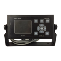
Details the main display, sidebar, and function of each key for system control.

Chapter 3: Alarm System

3.1 Alarm Indication

Describes audible and visual alarm notifications, including pending and acknowledged states.

Chapter 5: Installation

5.1 Mechanical Installation

Covers mounting requirements, alignment, and cable connection for the antenna unit.

5.2 Electrical Installation

Details wiring procedures, power configuration, and CDU setup for the system.

Chapter 6: System Configuration

6.1 Service Setup Menu

Provides access to system parameters for installation configuration via a password-protected menu.

6.2 GPS Setup

Configures GPS sources, antenna orientation, gyro orientation, and heading offsets.

Chapter 7: EM Sensor Calibration

7.1 Sensor Sensitivity Setting

Explains how to set the EM sensor's sensitivity value in the electronics unit for accurate speed readings.

7.2 Sensor Calibration

Details methods for calibrating the EM sensor using a table, zero point, or trial runs for optimal performance.

Chapter 8: Troubleshooting

8.1 Electronics Unit and CDU(s)

Guides basic checks for the electronics unit and CDUs, including component identification and LED indicators.

Chapter 9: Corrective Maintenance

Related product manuals