IM-P128-23 ST Issue 6
14
5.5 How to replace or clean the sensor:
-
Before starting any maintenance work make sure that the steam trap station is isolated
from the mains pressure (both steam and condensate) and that any residual pressure is
vented to atmosphere. Allow to cool before commencing work.
- If a waterlogging sensor is tted (WLSL1), it will be necessary to disconnect the wiring
at the terminal block. Remove the sensor (23 or 24) from the adaptor (20). (This can be
done in line so long as the adaptor is securely held in place).
- Clean the sensor insulation. If pitting of the insulation has occured, a new sensor should
be tted.
- Clean or replace the strainer screen (22) (whichever action is appropriate for the
condition of the screen).
- Replace the new or cleaned sensor (23 or 24) and screw it into the adaptor (20),
ensuring that the gasket (21) and strainer screen (22) are centralised.
- Tighten to the recommended torque, see Table 2.
- Reconnect the waterlogging sensor as described in IM-P087-34.
- Please note that the optional Spiratec SSL1 and WLSL1 sensors (items 20 + 23 or 24)
must not be fitted when the STS17.2 is installed in a vertical application. However
a sensor can be fitted to a UTD30 steam trap if fitted.
5.6 How to replace the check valve
Using a 32 mm A / F spanner, unscrew and remove the check valve blanking plug (16). You
can now see the check valve assembly (17) inside the body. A long 20 mm A/F socket is
required to unscrew the check valve (17) from the body.
Replace with a new check valve assembly (17) and tighten to the recommended torque:
110 - 120 N m (81 - 88 lbf ft).
Using a new gasket (18), replace the check valve blanking plug (16) and tighten to the
recommended torque, see Table 2.
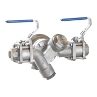
5.7 How to replace the ball valve spares (reference Figure 5):
Maintenance work can be carried out without removing the complete ball valve from the
pipeline. Remove the two upper bolts and nuts (12 + 13) and then loosen the lower
two (14 + 15). The complete body assembly (2) can can then be removed and any new
parts tted.
Renewal of seats:
1. Remove the body as described above.
2. With body removed, remove the seats (8).
3. Fit new seats, pushing them into the body recesses.
Renewal of the stem seals
1. Remove body as described above.
2. Remove nuts (5 and 11) and the belleville washers (10).
3. Replace stem seals (9).
Reassembly
Reassemble in reverse order to instructions given above. The ball valve bolts and
nuts (12 + 13 and 14 + 15) should be tightened to the recommended torques shown in
Table 2, page 15.
 Loading...