Operating and Installation Instructions, Form No. 102527, Back sheet 1 of 1
SPECIFICATIONS
NOTE:
●●
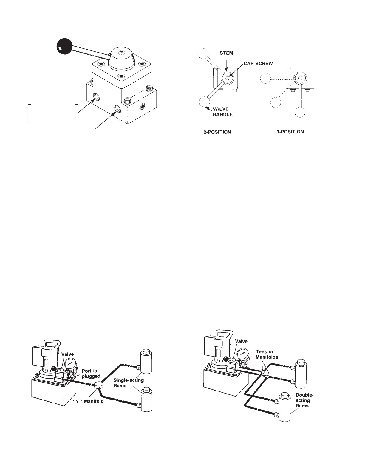
This valve is a low torque design for use with double-acting or single-acting cylinder(s).
●●
If this valve is to be used as a 3-way with single-acting cylinder(s), one port (A or B) must remain plugged.
●●
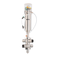
Valve handle can be moved to the desired position by loosening the cap screw and rotating in increments
of 22-1/2°. Torque cap screw to 60/80 in. lbs.
CONTROL VALVE SET-UP PROCEDURE
This pump-mounted valve can be connected in a variety of ways. The following steps will help ensure a safe, efficient,
and trouble-free set-up.
1. Remove port plugs form the pump, valve(s) and cylinder(s).
2. Seal all pipe connections with a high grade of thread sealant such as Power Team HTS6. Teflon tape can be used
if only one layer is applied carefully, two threads back, to prevent it from being pinched by the fitting and broken off
inside the pipe end. Loose pieces of tape could travel through the system and obstruct the flow of oil or cause
jamming of precision-fit parts.
3. Refer to the appropriate valve parts list for a hydraulic schematic.
4. For subplate-mounted valves, refer to Operating & Installation Instructions #102529 for mounting information.
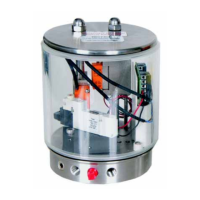
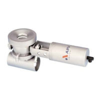
TYPICAL WORK HOLDING APPLICATIONS
Shown below are two typical work holding applications. Direct any questions about set-up to the appropriate
Technical Services staff as listed at the top of page 1 of 1.
SINGLE-ACTING CYLINDER(S) IN THE CIRCUIT DOUBLE-ACTING CYLINDER(S) IN THE CIRCUIT
CONTROLLED BY A PUMP-MOUNTED VALVE CONTROLLED BY A PUMP-MOUNTED VALVE
PORT "B"
Leave plugged if
using only one port
PORT "A"