© SPX Corporation
Sheet No.
Issue Date: 6-15-04, Rev. F
Parts List & Operating Instructions Form No. 106261
Operating Instructions
Removal
1. Refer to the vehicle service manual, and follow the manufacturer's recommended procedure to remove the
strut assembly from the vehicle.
2. Mark the position of the spring in relation to the lower platform and top mount; this notes the correct position
for installation.
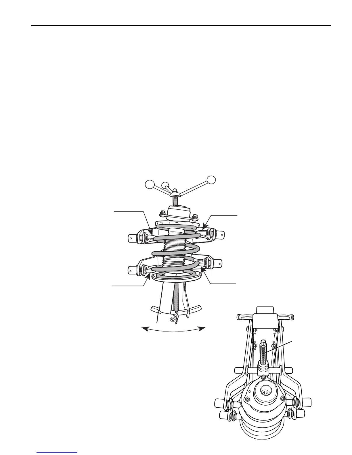
3. Choose the lowest possible spring coil to insert into the lower left jaw; tighten the locking ring. See Fig. 1.
4. Load the opposite side of the same coil in the lower right jaw; tighten the locking ring.
Note: It may be
necessary to move the compressor arms to access the coil.
5. Choose the highest possible spring coil to insert into the upper left jaw; tighten the locking ring.
6. Load the opposite side of the same coil in the upper right jaw; tighten the locking ring.
Note: OTC Bridge Accessory No. 6270 is designed to be used with the StrutTamer on strut springs that cannot
be compressed enough to remove the retaining nut.
7. Before servicing the strut assembly, align the strut spring with the forcing screw on the StrutTamer as
shown in Figure 1. Use the notched adjustment cradle to align the spring—simply lift up on the strut or the
lower arms, and move the cradle.
2 of 2
8. Equally space the top arms on the top trunnion as shown in
Fig. 2. The forcing screw must be centered between the two
top arms.
9. Operate the actuating screw to compress the spring only until
the strut cartridge is loose in the spring mounts. IMPORTANT:
It is not necessary to overcompress the spring. The
spring should be compressed only until the strut tube is
loose in the spring.
10
.Remove the piston rod nut, and service the strut as required.
Center the
forcing screw
between the
two top arms.
ll
ll
l
Forcing
Screw
Figure 2
Fasten locking jaw
to low side of coil.
Fasten locking jaw
to low side of coil.
Fasten locking jaw to
high side of same coil.
Fasten locking jaw to
high side of same coil.
1
3
4
2
5
Lift and rock cradle to
align strut spring with
StrutTamer forcing screw.
Figure 1