Do you have a question about the SRM ORIGIN PowerMeter and is the answer not in the manual?
Check chain catcher alignment, chainring seating, and bolt torque before PowerMeter installation.
Steps for installing the PowerMeter onto the frame and bottom bracket, including spacer and bolt tightening.
Guidance on fitting pedals, selecting crank length, and proper torque application for pedals.
Instructions for positioning and attaching the cadence magnet, including methods for different frame types.
Information on connecting the PowerMeter to SRM PowerControl or other ANT+ devices.
Details on how battery status is communicated and the procedure for battery replacement.
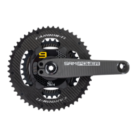
The SRM ORIGIN PowerMeter is a sophisticated device designed to accurately measure power output and cadence during cycling, providing crucial data for training and performance analysis. It integrates seamlessly into a bicycle's crankset, offering a robust and reliable solution for cyclists seeking precise performance metrics.
At its core, the SRM ORIGIN PowerMeter functions by measuring the force applied to the pedals and the rotational speed of the crankset. This data is then processed to calculate power output in watts and cadence in revolutions per minute (RPM). The device utilizes strain gauges embedded within the crank spider to detect minute deflections caused by pedaling force. These deflections are converted into electrical signals, which are then transmitted wirelessly to a compatible head unit, such as an SRM PowerControl or other ANT+ enabled devices. The PowerMeter is designed to provide highly accurate and consistent data, essential for effective training and race strategy. Its integrated design ensures that the measurement is taken directly at the source of power generation, minimizing external influences and maximizing data integrity. The device is also engineered to be robust and durable, capable of withstanding the rigors of various cycling environments, from road racing to off-road trails.
The SRM ORIGIN PowerMeter is designed for ease of integration and use, though its initial installation requires careful attention to detail. The device is compatible with a wide range of bottom bracket types, necessitating specific spacer configurations to ensure proper fit and function. Before installation, it's crucial to inspect the chainrings, ensuring they are flat, tight, and torqued to the correct specifications. The drive-side crankarm comes pre-installed with the PowerMeter, and it's critical not to loosen the pinch or crank bolt on this side to avoid damage.
Installation of the PowerMeter involves mounting it onto a suitable 30mm bottom bracket. The process requires installing the correct spacers on both the drive and non-drive sides, applying a small amount of grease to contact surfaces, and carefully seating the crank in the bottom bracket. The non-drive side crank is then rotated 180 degrees relative to the drive-side crankarm, and the axle bolt is lightly tightened with a thread locker. It's important to tighten the axle bolt only until the spacers touch the bottom bracket and there is no play, avoiding excessive force that could damage bearings.
Pedal installation is another key step, allowing for crank length adjustment from 170mm to 175mm. Before installing pedals, the Tri-lobe nut, washer, and contacting crank surfaces must be degreased and cleaned to prevent damage. Specific Tri-lobe nuts are used for the drive and non-drive sides, and the washer must be correctly aligned and flush inside the crank. Pedals are then tightened to the manufacturer's recommended torque.
For cadence measurement, a magnet needs to be installed on the frame, typically on the underside of the bottom bracket shell, positioned between 21-51mm from the center point. This magnet interacts with a sensor in the PowerMeter to register each crank revolution. There are two primary methods for magnet installation: under a cable guide (if present) or directly to the frame using double-sided tape. When using a cable guide, the magnet is placed beneath it and secured by the cable guide bolt, ensuring it is 4-6mm from the backside of the PowerMeter. If no cable guide is present, the magnet is cleaned with isopropanol alcohol and affixed to the frame with double-sided tape, again maintaining the 4-6mm distance from the PowerMeter. It's recommended to temporarily fix the magnet and confirm its correct position and functionality before permanently gluing it.
Once installed, the PowerMeter connects wirelessly to compatible ANT+ devices. To activate the PowerMeter and enable pairing, the crank needs to be spun 1-2 revolutions. This ensures the device is powered on and ready to transmit data.
Regular maintenance and inspection are crucial for the longevity and accurate performance of the SRM ORIGIN PowerMeter. After the initial 100km ride, and subsequently at regular intervals of 2,500km, all screw connections should be checked for correct torque specifications. If necessary, screws should be re-tightened, and thread locker replaced. Failure to observe these torque specifications can lead to loosened screw connections, which could result in product damage, injury, or even death.
The PowerMeter broadcasts its battery status to connected ANT+ devices, notifying the user when the battery is running low. Battery replacement should only be performed by authorized SRM Dealers or Service Centers. Unauthorized opening or replacement of the battery can lead to water leakage, permanent damage, and poses a danger of explosion. The device is equipped with lithium batteries that require specialized handling.
The SRM ORIGIN PowerMeter is designed to be a sealed unit to protect its sensitive electronics from environmental elements. Therefore, unauthorized opening and closing of the PowerMeter are strictly prohibited as this can compromise its water resistance and lead to permanent damage, voiding the warranty. For any issues or repairs, it is essential to consult an authorized SRM dealer or service center.
Disposal of the device should be done according to local and federal regulations for electronic waste. Users can return the device to their nearest SRM Service Center for proper disposal, ensuring environmentally responsible end-of-life management.
| Measurement Method | Strain Gauge |
|---|---|
| Cadence Measurement | Yes |
| Compatibility | ANT+, Bluetooth |
| Data Transmission | ANT+, Bluetooth |
| Measurement Range | 0-2000W |