0-4
REXTON 2007.09
0000-00
GENERAL INFORMATION
3) CIRCUIT IDENTIFICATION SYMBOL
Identification Symbol Meaning
C Connector
D Diode
Ef Fuse in engine room fuse & relay box
F Fuse in passenger room fuse box
G Ground
S Splice pack (Junction connector)
5) WIRING HARNESS COLOR IDENTIFICATION
Abbreviation Color Abbreviation Color
Br Brown Sb Sky Blue
G Green R Red
V Violet L Blue
P Pink Y Yellow
W White Gr Gray
Or Orange B Black
Lg Light Green
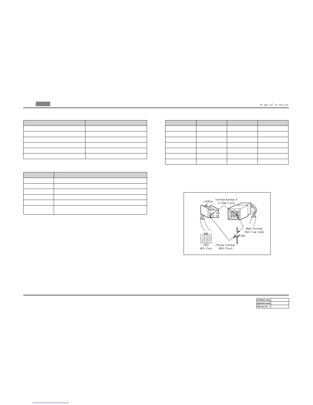
6) HOW TO CHECK TERMINAL NUMBER OF CONNECTOR
Terminal number is given based on Female Terminal Male Connector
▶
ex) Terminal Number 4 of C901 connection-
Power supply No. Power supply condition
15 Battery Voltage (B+) supply in Ignition Switch “ON” and “ST” (IGN
1)
15A Battery Voltage (B+) supply in Ignition Switch “ON” (IGN 2)
15C Battery Voltage (B+) supply in Ignition Switch “ON” and “ACC”
30 Battery Voltage (B+) supply directly regardless of Ignition Switch
31 Ground connected to battery (-)
58
Battery Voltage (B+) supply in Head Lamp Switch 1st and 2nd step
(Illumination circuit)
4) FUNCTION OF POWER SUPPLY LINE (NUMBER)
 Loading...