43
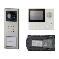
AS-TVHa-1/1 Siedle Vario with
Intercomfunctions
Functional characteristics
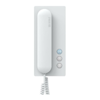
Calling and speech and video
between the door station and the
connected handsfree bus telephones
BFCV 850-... with colour monitor.
An existing call cannot be listened
into from other handsfree bus
telephones.
Door release button for the door
release function, light button for the
light switching function. Pressing
the monitor button will show the
camera picture from the door station
which placed the last door call.
Connection of a storey call button
(ERT) for calling from an apartment
door or storey door.
Ring tones can be selected for calls
from the front door, apartment door
or internal calls.
Additional connection of other bus
telephones with colour monitor
when looping through from one
device to the next. Other bus door
loudspeakers with video are con-
nected with bus video distributors
BVVU 650-... or BVVS 650-...
Basic functions with all bus tel-
ephones
Internal speech communication pos-
sible between all bus telephones
BTS/BFS/BTC/BFC/BTSV/BFSV/BTCV/
BFCV 850-..., switching and control
functions possible with bus
switching modules BSM 650-...,
BSE 650-... and BEM 650-...,
feedback to bus telephones by
means of LED can be programmed.
Secondary signal unit BNS 750-...
possible. Parallel door call to up to 8
BFCV 850-... units possible, see also
chapter 7, page 82.
Selective dialling of the door sta-
tion possible using additional free
buttons.
Additional intercomfunctions
With handsfree bus telephones
BFCV 850-..., additional convenience
functions are possible for internal
communication.
• Internal call with callback function
• Automatic call pick-up of internal
calls
• Internal group call
• Collective paging announcement
(*only with supplementary supply)
• Video memory function
possible with the bus telephone
BTCV/BFCV 850-..., additional
installation required.
Remarks
a) The TR 603-... (12 V AC, 1.3 A)
can supply 1 door release button
and max. 24 bus call button
modules with LED lighting
(BTM 650-01, -02, -03 and -04).
With more than 24 illuminated bus
call button modules, an additional
TR 603-... is required.
Current consumers in the
AS diagram:
Door release appr. 600 mA
Camera heating 100 mA
LED lighting per bus call button
module 20 mA
b) Door release contact load in the
bus video line rectier BVNG 650-...
max. 15 V AC, 30 V DC, 2 A.
• Light contact load in the bus video
line rectier max. 15 V AC, 30 V DC,
2 A.
c) Door release 12 V AC, use at least
20 Ohm, (e.g. TÖ 615-...), for pos-
sible connection variants see chapter
8, page 92.
d) Conductor length bus telephone -
storey call button ERT max. 50 m.
e) When using the internal video
memory module, the bus telephone
BTCV/BFCV 850-... must be supplied
by an additional direct voltage
(20 - 30 V DC, 350 mA).
NG 602-... or VNG 602-... can be
used for this purpose. Connection of
the supply at terminals +M/-M. For
more information, see chapter 8,
page 94.
Installation
In each bus telephone with colour
monitor, there is a terminating circuit
board connected in the as-delivered
status in the centre of the
connecting terminals TaM and TbM.
This circuit board is an RC element
which comprises a resistor with
100 Ohm and a capacitor 1 nF.
When looping through from one
bus telephone to the next in the
installation, this terminating circuit
board must be removed. If, however,
bus distributors are used in the
installation, or if there is only 1 bus
telephone with colour monitor in
the line, the terminating element
remains in the bus telephone.
Terminal
BTSV/BFSV/BTCV/BFCV 850-...
Connection for one bus telephone
or the last bus telephone in the line.
Connection when looping
through from one bus telephone to
another.
Cable laying
Only signals from the In-Home bus
may be transmitted via the laid
conductor material. No additional
transmission is possible, for instance
to PBX extensions of a telephone
system or an S0 bus (ISDN). The
camera branch and monitor branch
must be laid in a separate cable
and must not be installed inside the
same conduit. This can result in dis-
turbance to the picture composition.
 Loading...