Do you have a question about the ST Group PIRANHA ST 500 and is the answer not in the manual?
Device's intended use for detecting and locating eavesdropping devices.
Lists technical specifications and included components of the ST 500 device.
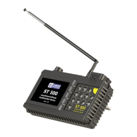
Details main unit functions, components, and associated accessories.
Explains device battery operation, charging, and power indicators.
Provides detailed technical parameters for each detection channel and overall specs.
Instructions for powering the device on and off, and initial display.
Describes the main menu for selecting operation channels and settings.
Explains the elements displayed in the device's status bar.
Details how to access and use the settings menu for date, time, and language.
Guide to setting the device's date using the interface.
Guide to setting the device's time using the interface.
Instructions for changing the device's interface language.
Default mode showing all frequency band activity.
Isolates signals by comparing scan cycles, highlighting new signals.
Analyzes signals at a specific frequency by tuning and research.
Sets a baseline to display only signal level differences.
Analyzes demodulated signals using an oscilloscope display.
Registers signals exceeding a threshold, categorizing them.
Fine-tunes frequency to a detected signal for detailed analysis.
Monitors frequency bands for digital communication standards.
Detects and analyzes signals from active mobile digital devices.
Identifies and analyzes signals from mobile communication base stations.
Detects transmitters in user-defined frequency ranges.
Provides precise signal frequency determination and analysis.
Helps locate IR signal sources by setting detected signal level to zero.
Details connecting the device to electric mains via an adapter.
Explains connecting to LAN cables using RJ45 plugs.
Describes connecting to telephone lines with RJ11 plugs or sockets.
Covers connecting to raw-ended low current cables using a special adapter.
Selects the type of circuit to test: electric mains or low current.
Chooses the frequency band for signal search (0.1-60 MHz or 0.1-180 MHz).
Displays all signal activity in the circuit for electric mains testing.
Reduces interference and evaluates changes by setting previous signals to "0".
Studies signals in PANORAMA/DIFFERENTIAL modes, allowing listening and analysis.
Analyzes signals at a fixed frequency using an oscilloscope display.
Registers signals exceeding an adaptive detection threshold.
Fine-tunes frequency to obtain maximum response on the signal strength bar.
Analyzes demodulated signals in AUTOMATED mode.
Displays wire combinations and voltage values for low current circuits.
Sets up the electronic switch for testing low current multiwire cables.
Displays frequency band activity for low current circuit testing.
Starts the electronic switch control mode for wire pair analysis.
Configures the electronic switch for specific cable types and pin assignments.
Adjusts the gain multiplier for signal amplification.
Applies bias voltage to connected wire pairs for microphone testing.
Cycles through all wire pair combinations for automated testing.
Activates oscilloscope for signal analysis in control or automated mode.
Activates spectrum analyzer from the oscilloscope for frequency analysis.
Outlines the software's purpose for signal analysis and firmware updates.
Describes user actions like adjusting settings and managing data files.
Specifies system requirements for running the ST 500 software.
Provides step-by-step instructions for installing the ST 500 software on a PC.
Shows the PC software interface and explains its elements.
Lists and describes the various operation modes available in the software.
Defines frequency band limits for "THREAT" or "NON-THREAT" signal detection.
Creates and edits frequency bands for mobile communication systems.
Creates and edits frequency bands for mobile communication systems.
Creates and edits frequency bands of specific interest to the user.
Details how to update the device's firmware using the PC software.
Covers detection, identification, and localization of radio transmitting devices.
Details the search algorithm for using the Automated mode.
Explains searching in Panorama and Differential modes under heavy traffic.
Monitors frequency bands for specific digital communication standards.
Describes methods for locating the source of detected signals.
Covers detection and location of infrared transmission eavesdropping devices.
Methods for identifying and excluding false signals during IR detection.
Guides detection of wired transmitters in electric mains and low current circuits.
Outlines the procedure for testing electric mains for HF signals.
Details testing low current circuits and telephone lines for signals.
Guides detection of low-frequency signals from wired microphones.
Explains how to search for active microphones in analog telephone lines.
Details applying bias voltage to detect electret microphones.
Methods for locating signal sources detected by WR or LFA channels.
Describes the acoustic method for locating signal sources.
Explains localization using ST 500 and an NLJD.
Explains basic settings like channel selection, date, time, and language.
Details controls and functions for the Selective HF Detector.
Lists controls and functions for the IR Detector channel.
Details controls and functions for the Wired Receiver channel.
Details controls and functions for the Low Frequency Amplifier channel.
Describes the 8P8C connection for computer 8-wire lines.
Describes the 6P6C connection for 6-wire telephone lines.
Describes the 6P4C connection for 4-wire telephone lines.
Describes the 6P2C connection for 2-wire telephone lines.
Explains manual setup for arbitrary 4-wire lines without connectors.
Explains the nature and use of twisted pair cables.
Details various RJ connector standards and their purposes.
Describes wiring schemes for four-pair cables like 568A and 568B.
Details the EIA/TIA-568A wiring scheme for network cables.
Details the EIA/TIA-568B wiring scheme for network cables.
Explains crossover wiring for connecting network devices.
Illustrates wiring schemes for cables with fewer twisted pairs.
Provides information on analog, hybrid, and digital PBXs and telephone lines.
| Type | Laser Distance Meter |
|---|---|
| Accuracy | ±1.5mm |
| Laser Class | Class 2 |
| Laser Type | 635 nm, <1 mW |
| Display | LCD with backlight |
| Operating Temperature | 0°C to 40°C |
| Protection Class | IP54 |
| Dimensions | 122 x 50 x 28mm |
| Weight | 120g (with battery) |
| Units of Measurement | m, in, ft |
| Battery Type | 2 x AAA |
| Battery Life | Up to 5000 measurements |