Do you have a question about the St. Jude Medical EP-4 Series and is the answer not in the manual?
| Model | EP-4 Series |
|---|---|
| Type | Electrophysiology System |
| Manufacturer | St. Jude Medical |
| Channels | 64 |
| Display | High-resolution touchscreen |
| Data Storage | Internal storage with export options |
| Connectivity | Network |
| Compatibility | Compatible with various |
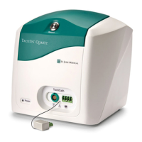
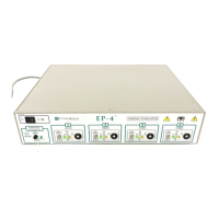
Describes the EP-4 stimulation module, its AC power, touch screen, and keyboard components.
Details the EP-4 stimulator's purpose for diagnostic electrical stimulation of the heart.
Explains warning labels and symbols on the EP-4 device for operator guidance and safety.
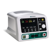
Details the layout and components of the EP-4 stimulation module's front panel, including outputs and indicators.
Details the emergency stimulation button for providing constant pacing across all channels.
Explains the AC line power connection, voltage range, and the mains power switch location.
Identifies the DSUB connector for communication between the stimulation module and the computer terminal.
Describes the ECG input for synchronization, its isolation warning, and connection guidelines.
Explains back panel outputs for chart recorder markers and controlling paper advance.
Details the chassis grounding terminal for equipotential connection and case grounding.
Describes the rotary knob to adjust the volume of beep tones emitted by the stimulator.
Details the EP-4 keyboard layout, including standard typewriter keys and dedicated stimulation keys.
Explains the main menu screen, listing protocol select keys and their corresponding functions.
Describes the self-test process for the computer and stimulation module upon system startup.