Do you have a question about the Stanford Research Systems SR570 and is the answer not in the manual?
Overview of the SR570's purpose and basic operation.
Detailed explanation of front panel buttons, LEDs, and their functions.
Description of rear panel connectors, inputs, and outputs.
Information on battery care, charging, and usage for the SR570.
Introduction to the SR570's remote programming capabilities via RS-232.
Comprehensive reference for SR570 RS-232 commands.
Code examples for controlling the SR570 using BASIC and C.
Detailed explanation of the SR570's internal circuit blocks and their functions.
Procedures for calibration, component replacement, and repair.
Discussion of various noise sources affecting the SR570's performance.
Visual representation of the SR570's internal circuits with corresponding sheet numbers.
Instructions for selecting AC input voltage and the correct fuse.
Guidelines for connecting instruments and ensuring proper ventilation.
Steps for powering on the SR570 and understanding default settings.
Warnings for repackaging, biomedical use, and photomultipliers.
List of accessories and specified environmental conditions.
Precautions for maintaining the SR570's batteries.
Explanation of common symbols found on SRS products.
Details on input impedance, offset, noise, sensitivity, and filter types.
Specifications for gain allocation, output drive, and RS-232 interface.
Overall operating temperatures, power, dimensions, weight, and warranty.
Graphs showing typical amplifier bandwidth for various sensitivity settings.
Graphs illustrating current noise as a function of frequency.
Table summarizing bandwidth, noise, temp. coefficient, and impedance.
Step-by-step guide to verify SR570 specifications.
Key considerations for accurate specification verification and sensitive measurements.
Rules for formatting RS-232 commands for the SR570.
Organized commands for sensitivity, offset, bias, filters, and others.
Explains the necessity and benefits of current amplifiers.
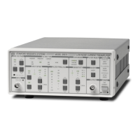
General description of the SR570's capabilities and architecture.
Step-by-step guide to quickly orient the user with the instrument's features.
A visual block diagram illustrating the SR570's internal signal flow.
Labeled image of the SR570 front panel with controls and indicators.
General overview of front panel operations and RS-232 control.
Details on powering the SR570, battery operation, and charging indicators.
Connecting signals and using the FREQ COMP potentiometer.
How to reset the SR570 to its factory default settings.
Setting and using bias voltage and input offset current.
Inverting output and selecting filter types.
Adjusting sensitivity and selecting gain modes.
Output specifications and using the filter reset function.
Explanation of the SR570's status indicator LEDs.
Details on the power entry module, fuse, and voltage selection.
Description of the external DC power output jacks.
Explanation of the CHARGE and MAINTAIN LEDs and battery charging logic.
Using TTL inputs for blanking and toggling signal polarity.
Details on the RS-232 serial interface for communication and control.
Guidelines for powering the SR570 and maintaining battery health.
Advice on avoiding deep discharge, idle damage, and temperature issues.
Recommendations for storing batteries and inspecting for leakage.
Introduction to the SR570's remote programming capabilities via RS-232.
Rules for formatting RS-232 commands for the SR570.
Commands to set and control amplifier sensitivity.
Commands for managing input offset current.
Commands to control the input bias voltage.
Commands for configuring the low-pass and high-pass filters.
Miscellaneous commands for SR570 control.
Example code for controlling the SR570 using IBM PC BASIC.
Example code for controlling the SR570 using Microsoft C.
Detailed description of the front-end amplifier circuit and its components.
Explanation of the two filter stages and gain configuration.
Description of the SR570's output amplification and vernier stages.
How the SR570 detects and indicates signal overload conditions.
Details on the SR570's microprocessor, memory, and control logic.
Explanation of the battery charging circuitry and power regulation.
Description of the SR570's internal voltage regulator circuits.
Details on optically isolated rear panel interfaces.
Information on battery construction and the Power Entry Module.
Description of front panel pushbuttons, LEDs, and controls.
Step-by-step guide for calibrating various voltages on the SR570.
Guidance on replacing damaged front-end op amps.
When and how to replace the SR570's internal batteries.
Instructions for replacing fuses in the SR570.
Discussion of noise sources affecting the amplifier's input stage.
Explanation of Johnson noise and shot noise as intrinsic noise types.
Detailed explanation of Johnson noise voltage and current.
Detailed explanation of shot noise in electric current.
Discussion of 1/f noise in resistors and other sources.
How to calculate total noise from incoherent sources.
Identification and minimization of external noise sources.
How AC voltage couples via stray capacitance and its cures.
How magnetic fields induce noise and methods to reduce it.
Noise generated by ground connections and loop issues, with cures.
How mechanical vibrations translate into electrical noise.
Strategies to reduce noise caused by microphonic effects.
Noise generated by junctions between dissimilar metals.
Methods to reduce noise from thermocouple effects.
Explanation of how SR570 baluns reduce ground loop effects.
Table showing op-amp selection based on sensitivity and gain mode.
Explanation of dynamic reserve and its relationship to input signals and noise.
How gain distribution and filters manage dynamic reserve and prevent overload.
Graph showing dynamic reserve behavior across frequencies and gain modes.
How feedback capacitance affects amplifier response and compensation.
Impact of input capacitance on noise performance and measurement accuracy.
Precautions to minimize negative effects of input capacitance.
List of components for the SR570 main circuit board.
List of components for the SR570 front and rear panels.
List of miscellaneous hardware and chassis assembly parts.
| Input Current Range | 1 pA to 1 mA |
|---|---|
| Input Resistance | 1 kΩ |
| Output Voltage | ±10 V |
| Output Current | ±10 mA |
| Type | Current Amplifier |
| Bandwidth | DC to 1 MHz |
| Noise | 4 fA/√Hz |
| Input Noise | 4 fA/√Hz |
| Power Supply | 100-240 VAC, 50/60 Hz |
| Dimensions | 3.5" x 19" x 12" |