EasyManua.ls Logo

Stanley BEST SSS-SEDA User Manual

Stanley BEST SSS-SEDA
4 pages
To Next Page IconTo Next Page
Page #1 background imageLoading...
Page #1 background image
INS SSS-SEDA v6.0.vsd Created: 9/23/2009 Revised:5/27/2010 INS0000130-01 v1.0 Page 1
SSS-SEDA (Emergency Door Alarm)
Packing List
Telescoping Sensor & Fasteners
Controller x 1 each
# 8 Wood Screws
x 3 each
10-24 Carriage Bolt, Hex Nuts,
Washers & Lock Washers x 4 each
8 – 32 x 3/16" Pan Head Phillips Screws, #8 Washers x 2
each & Mounting Plate Spacer x 1 each
Wire Harness x 1 each
Telescoping Sensor x 1 each
6 – 32 x ½” Flat Head Security Screw x 2
each, Cylindrical Locking Ring x 1 each &
Re – Set Key Switch x 1 each
Power Supply x 1 each
#8 Wood Screws & Plastic
Anchors x 8 each
Console x 1 each
Flashing Amber Light x 1 each &
#10-32 Nuts, Split Washer & Flat Washer x 2 each
Top Portion
Bottom Portion
Full Mortise Hinge x 1 each
12-24 x ½” Torx Flat
Head Screw x 15 each
#10-¾” self Drilling Screw
X 4 each
¼ - 20 x 1" Torx Flat
Head Screw
x 9 each
¼ - 20 x 1-5/8" Sex Bolt
x 9 each
BEST ACCESS SYSTEMS
A Product Line of Stanley Security Solutions, Inc
Indianapolis, IN - 46250
(800)-392-5209
Question and Answer IconNeed help?

Do you have a question about the Stanley BEST SSS-SEDA and is the answer not in the manual?

Stanley BEST SSS-SEDA Specifications

General IconGeneral
BrandStanley
ModelBEST SSS-SEDA
CategorySecurity System
LanguageEnglish

Summary

Installation Instructions

Full Mortise Hinge

Instructions for installing the full mortise hinge. Refer to a separate sheet for detailed steps.

Power Supply and Controller Installation

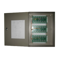
Install the power supply and controller, connect the console, and power up. Verify all LEDs turn green.

Strobe Installation

Mount the strobe on the ceiling and run wires to the controller, observing polarity.

Key Switch Installation

Add a mortise cylinder and mount the key switch on a single gang box at the door.

Door Sensor Installation Steps

Detailed steps for mounting and adjusting the door sensor on the door and frame.

Door Sensor Testing and Adjustment

Sensor Cover and Mounting Plate Adjustment

Secure the sensor cover to the mounting plate and adjust sensitivity using allen head screws.

Sensitivity Testing and Adjustment

Test sensor operation, adjust sensitivity based on LED feedback and sensor depress tests.

Wiring Information

SEDA Schematic

Diagram illustrating the wiring connections for the SEDA system components.

Related product manuals