15
ENGLISH
the guide bar and the saw chain on the underside as shown
in Fig.G.
2. To adjust saw chain tension, loosen hex head
screws
12
.
3. Rotate the screw
19
in the front of the housing using the
flat screwdriver end of thewrench.
4. Do not over‑tension the saw chain as this will lead to
excessive wear and will reduce the life of the guide bar and
saw chain. Overtensioning also reduces the amount of cuts
you will get per batterycharge.
5. Once saw chain tension is correct, tighten hex head
screws
12
to clampbar.
6. When the saw chain is new check the tension frequently
(after disconnecting battery) during the first 2 hours of use
as a new chain stretchesslightly.
NOTE: Saw chain tension should be adjustedregularly.
Chain Oiling (Fig. H)
1. A high quality bar and chain oil or SAE30 weight motor
oil should be used for saw chain
14
and guide bar
13
lubrication. The use of a vegetable based bar and chain
oil is recommended when pruning trees. Mineral oil is not
recommended because it may harm trees. Never use waste
oil or very thick oil. These may damage your polesaw.
2. Lubricate the whole saw chain evenly before each use as
shown in FigureH. Also lubricate the saw chain whenever
replacing a fully discharged battery with a fully chargedone.
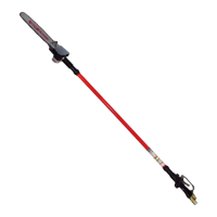
Transporting Pole Saw (Fig. A)
Always remove the battery pack
6
from the handle and cover
the saw chain
14
with the scabbard
15
when transporting the
pole saw.
Joining Saw Head Module to Handle Module
(Fig. I–L)
WARNING: Sharp moving blade. To prevent accidental
operation, insure that battery is disconnected from the
handle and that the protective scabbard is in place on the
chain before performing the following operations. Failure
to do this could result in serious personal injury.
The three assembliess which make up the pole saw are keyed
to insure correct assembly. If an assembly does not smoothly
attach to another do not force fit.
Combining the handle assembly
1
to the saw head
assembly
3
creates a pole saw that is approximately 1.8m in
length as shown in Fig. I.
To attach the handle assembly to the saw head assembly:
1. Align the groove
21
on the outside of the coupling end of
the handle assembly
1
with the tongue
22
on the inside
of the coupling end of the saw head assembly
3
. Refer to
Fig.J. Push the two sections completelytogether. Refer to
Fig.K.
2. Slide the threaded sleeve
9
on the saw head assembly
down as far as possible and rotate the sleeve clockwise
until it stops and completely covers the threads as shown
in Fig.L.
WARNING: Always check to make sure that the sleeve
is completely threaded on and that the red threads are
no longer visible. Not threading the sleeve completely
on could result in the assemblys becoming disconnected
creating a hazardous condition. Periodically check the
connections to insure that no red threads arevisible.
Joining Center Extension to Saw Head
Module and Handle Module (Fig. A, M)
Adding the center extension
2
to the handle assembly
1
and
saw head assembly
3
creates a pole saw that is approximately
2.7 m in length as shown in Fig.M.
Refer to to Joining Saw Head Module to HandleModule for
directions on how to attach the middle assembly to the handle
assembly and saw headassembly.
WARNING: Always check to make sure that the sleeve
is completely threaded on and that the red threads are
no longer visible. Not threading the sleeve completely
on could result in the assemblys becoming disconnected
creating a hazardous condition. Periodically check the
connections to insure that no red threads arevisible.
DISASSEMBLY
WARNING: To reduce the risk of serious personal
injury, turn unit off and before making any
adjustments or removing/installing attachments or
accessories. An accidental can causeinjury.
Detaching Saw Head Module (Fig. N)
WARNING: Sharp moving blade. To prevent accidental
operation, insure that battery is disconnected from the
handle and that the protective scabbard is in place on the
chain before performing the following operations. Failure
to do this could result in serious personal injury.
When detaching the assemblies, whether it is in the two
assembly or three assembly mode, always detach the saw head
assembly
3
first. To do this, rest the handle assembly
1
on the
ground and grasp the center of the saw head assembly with
one hand as shown in Fig.N. Use your other hand to loosen the
threaded sleeve and then pull the two halves apart. Repeat this
process if the center extension wasattached.
OPERATION
Instructions for Use
WARNING: Always observe the safety instructions and
applicableregulations.
WARNING: To reduce the risk of serious personal
injury, turn tool off and disconnect before
making any adjustments or removing/installing
attachments or accessories. An accidental start-up can
causeinjury.
Proper Hand Position (Fig. O)
WARNING: To reduce the risk of serious personal injury,
ALWAYS use proper hand position asshown.
 Loading...