CONNECTION DIAGRAM CONFIGURATION SMS COMMANDS LIST REGISTRATION
SIM card installation
Open tracker housing up with at item and insert SIM card in
the slot on the circuit board. Put the plastic cover back.
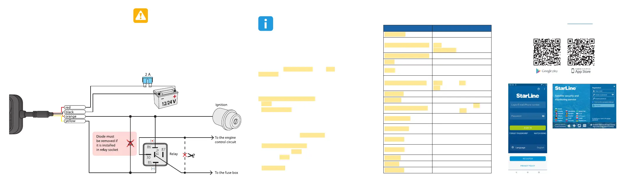
This wiring must be done by qualied technician.
1. Install StarLine 2 app or browse starline.online web service
2. Register a new StarLine account
3. Select Add device menu and follow the guide
Prior to conguration make connections wiring and
give power supply.
Record an owner phone number (SOS1) to device memory to
be able control tracker and receive notications.
All commands from SOS-number are sent without GSM
password. Commands from other phones must be added with
the GSM password between command text with comma and
# symbol. For example, to request current position send the
following text POSITION,1234#, where 1234 — GSM password,
POSITION# — command text.
To record an owner phone number as SOS number (if not
saved yet), or change SOS number without access to previously
saved one, send the text command
SOS,XXXX,A,+XXXXXXXXXX#, where
• ХХХХ — GSM password (4 digits, by default 1234),
• +XXXXXXXXXX — telephone number in international
format that must be saved as SOS-number.
To change GSM-password after setting SOS-number make
following:
• Send SMS-command PWDSW,OFF#
• After receiving a responding message send SMS command
PASSWORD,XXXX,YYYY#,
where XXXX – 4 digits of currentGSM password,
YYYY – 4 digits of new GSM password
• After receiving a responding message send SMS command
PWDSW,ON#
SMS commands Description
POSITION# Request current location
SOS,XXXX,A,+XXXXXXXXXX#
Set owner phone number, where
XXXX
- GSM password (default 1234),
+XXXXXXXXXX
- owner phone number
SOS,XXXX,D,+XXXXXXXXXX#
Delete owner phone number
SOS# Request owner phone numbers
IMEI#
Request device IMEI to register on starline.
online / mobile app
APN,NAME,LOG,PSW#
Set network access point, where:
NAME
- apn name,
LOG
- user login,
PSW
- password
GPRSSET# Request network status
STATUS# Request device status
PASSWORD,OLD,NEW#
Change GSM password, where
OLD
- old
(default) password,
NEW
- new password
PWDSW,OFF#
Switch GSM password O (from SOS1
owner number)
PWDSW,ON#
Switch GSM password On (from SOS1 owner
number)
PRELAY,1#
Activate universal output (from SOS1
number only)
PRELAY,0#
Deactivate universal output (from SOS1
number only)
PARAM# Request conguration parameters
RESET# Reboot device
FACTORY# Reset device to factory settings
Sample NC engine cut connection diagram
Universal output (yellow wire) can be used for remote
engine blocking like in example below. Max load for universal
output – 200 mA (–).
 Loading...