Use of Trademarks, Registered Trademarks, and other Protected Names and Symbols
This manual may make reference to trademarks, registered trademarks, and other protected names and/or symbols of third-party companies not related in any way to
StarTech.com. Where they occur these references are for illustrative purposes only and do not represent an endorsement of a product or service by StarTech.com, or an endorsement of the product(s)
to which this manual applies by the third-party company in question. Regardless of any direct acknowledgement elsewhere in the body of this document, StarTech.com hereby acknowledges that all
trademarks, registered trademarks, service marks, and other protected names and/or symbols contained in this manual and related documents are the property of their respective holders.
Technical Support
StarTech.com’s lifetime technical support is an integral part of our commitment to provide industry-leading solutions. If you ever need help with your product, visit www.startech.com/support and
access our comprehensive selection of online tools, documentation, and downloads.
For the latest drivers/software, please visit www.startech.com/downloads
Warranty Information
This product is backed by a two-year warranty.
StarTech.com warrants its products against defects in materials and workmanship for the periods noted, following the initial date of purchase. During this period, the products may be returned for
repair, or replacement with equivalent products at our discretion. The warranty covers parts and labor costs only. StarTech.com does not warrant its products from defects or damages arising from
misuse, abuse, alteration, or normal wear and tear.
Limitation of Liability
In no event shall the liability of StarTech.com Ltd. and StarTech.com USA LLP (or their ocers, directors, employees or agents) for any damages (whether direct or indirect, special, punitive, incidental,
consequential, or otherwise), loss of prots, loss of business, or any pecuniary loss, arising out of or related to the use of the product exceed the actual price paid for the product. Some states do not
allow the exclusion or limitation of incidental or consequential damages. If such laws apply, the limitations or exclusions contained in this statement may not apply to you.
before you tighten them.
5. After one side of the frame is fastened together, ip the frame
over and complete the instructions in step 4.
6. Tighten up all of the screws and nuts on both sides of the frame.
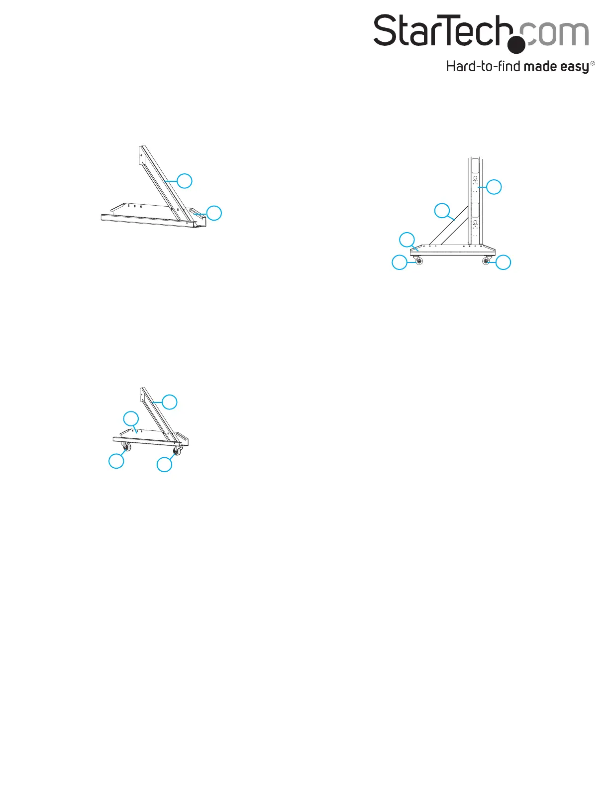
Assemble the bottom support beams
1. Place one of the angled support beams (D) on the inside of one of
the bottom support beams (A), making sure to line up the holes
on both beams.
2. Use the Allen key and two of the M6 screws and nuts to fasten the
angled support beam (D) to the bottom support beam (A). Make
sure to tighten the screws and nuts.
3. Place one of the heavy-duty casters (E) underneath the bottom
support beam (A) at the end closest to where the angled support
(D) beam is attached to the bottom support beam.
4. Line up the holes on the bottom support beam (A) with the holes
on the caster (E).
5. Use a Phillips screwdriver (not included) and four of the M6 Caster
Screws to fasten the caster (E) to the bottom support beam (A).
6. Place one of the heavy-duty locking casters (F) underneath the
bottom support beam (A) at the end farthest away from where
the angled support beam is attached to the bottom support
beam.
7. Line up the holes on the bottom support beam (A) with the holes
on the locking caster (F).
8. Use the Allen key and four of the M6 Caster Screws to fasten the
locking caster (F) to the bottom support beam (A).
9. Repeat steps 1 to 8 to assemble the second bottom support
beam.
Attach the bottom support beams to the frame
1. Lay the assembled frame onto its side, perpendicular to the oor.
2. Place one of the assembled bottom support beams (A) over the
corner of one edge of the frame, making sure that the frame is
sitting in the end closest to the locking caster (F).
3. Line up the holes on the assembled frame (B) with the holes on
the bottom support beam (A).
4. Use the Allen key and two of the M6 screws to attach the
assembled frame (B) to the bottom support beam (A).
5. Use the Allen key and two of the M6 screws to attach the angled
support beam (D) to the frame.
6. Repeat steps 1 to 5 to attach the second bottom support beam
(A) to the frame.
7. Stand the assembled rack up. If necessary, tighten any loose
screws or nuts.
Install equipment into the frame rack
• Using the M6 Rack Screws and the Plastic Washers, install your
equipment into the frame rack.
Warning! When installing equipment into the rack, start from the
bottom of the rack rst and move upwards, keeping the heaviest
equipment at the bottom to avoid a situation where the rack
becomes top heavy.
D
A
D
D
A
F
E
A
B
E F
 Loading...