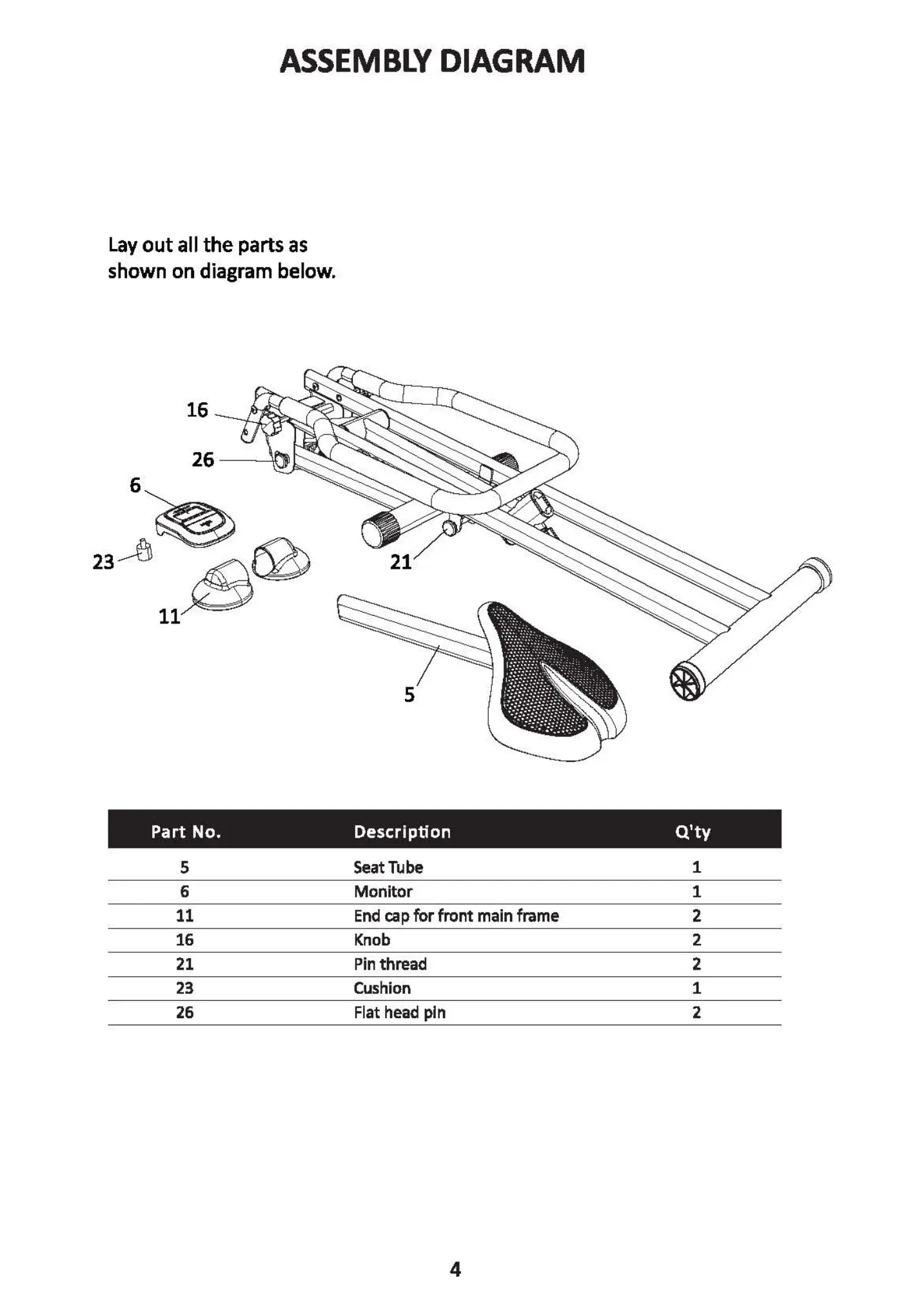
ASSEMBLY DIAGRAM
Lay out all the parts as
shown on diagram below.
16
26
6
23
11
Part No.
5
6
11
16
21
23
26
26
2
26
21
5
Description
Seat Tube
Monitor
End cap for front main frame
Knob
Pin thread
Cushion
Flat head pln
4
Q'ty
1
1
2
2
2
1
2
IMPORTANT
Please make sure the Flat head
pin(26) is tightly fastened.
STEP 2
O removethe protect cap(39)
3
ASSEMBLY
39
5
STEP 1
Releasethe Flat head pin(26) from
the machine, bring forward the
Rear Support Tube(2) then fasten
with the Flat head pin(26) .
26
Insert the End cap for front main
frame(ll) so the machine can be
free standing.
11
11