Solutions Strategies and Innovations
Static Solutions Inc. - Ohm - Stat RT - 1000 Information
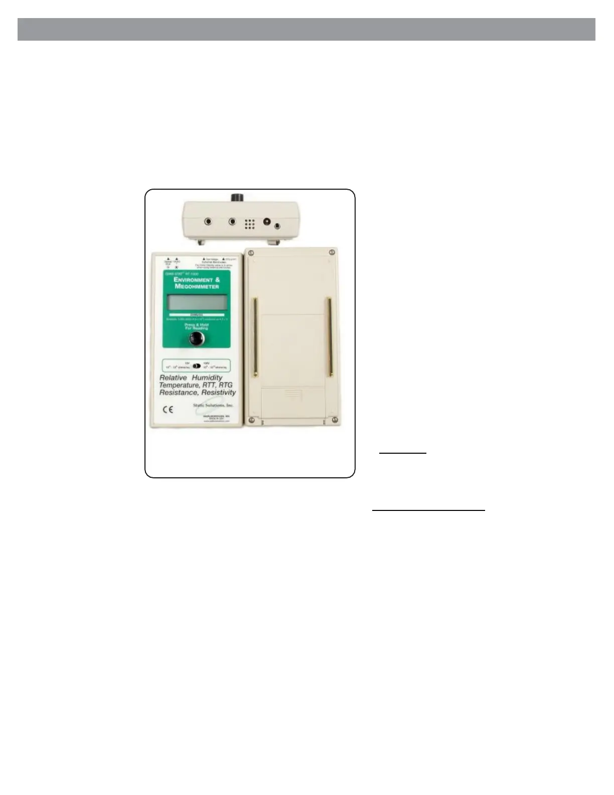
Ohm-Stat RT-1000 METER DESIGN FEATURES
A
Test Button- The round black button will turn on the power. When depressed
and held down with reasonable force the resistance/resistivity, humidity, and
temperature values are displayed on the screen for approximately 30 seconds.
HOLD THE BUTTON DOWN UNTIL THE VALUES ARE DISPLAYED. At the
completion of the test the power will turn off automatically.
B
Selector Switch- The switch selects the desired applied test voltage of either
10 or 100 volts.
10 volts should be used
between 1X 10
3
- 9.9 X 10
5
ohms. You can over ride the
D
range by selecting the 10 or
C
100 volt switch per EOS
standards.
100 volts should be used to
H
measure between
1 X10
6
–1 X10
13
ohms per
EOS standards.
If the battery is too low to
give accurate readings the
G
LCD will display “Low
Battery”
B
If the resistivity is below 10
3
ohms/sq., the LCD will
Display “less than 1K”.
F
If the reading is over 10
12
Battery Compartment- This
F
compartment houses a 9 volt battery
which must be installed prior to use.
Use a 9 volt alkaline battery for long
life. Do not use the alkaline battery if
the power battery is used. If the
power adapter is used a rechargeable
battery is recommended.
G Parallel Test Probes- These
probes located on the bottom of the
meter are used to measure surface
resistiviy in ohms/sq. units. These
probes are made from a highly
conductive, low durometer elastomer.
Care should be taken to avoid harsh
solvents and extreme abrasion.
Occasional cleaning with a mild soap
and water solution will extend the life
of the probe feet. If damage does
occur, these probes are replaceable
for a nominal charge. The probes are
fabricated with an internal and
external brass rails.
H
Case- The meter case is molded
from a high impact ABS polymer.
Simple cleaning with a mild soap and
water solution will remove all dirt and
ohms/sq. the LCD will
Figure 2 - Features of the Ohm - Stat RT 1000
debris.
display “more than 2 X 10
12
.
Temperature - Humidity - Resistance Meter
If the reading is over 10
6
ohms/sq. the LCD will display “change to
100 volt setting” if the setting is set on 10 volts. If the reading is
under 10
6
ohms/sq. the LCD will display “change to 10 volts “ if the
meter voltage switch is set on 100 volts.
C
External Test Jacks- The external 3.5 mm monaural jacks on the
top right of the meter are used to attach the two coil cords to the
2.5 inch-5 lb. probes These probes are used to test resistance
and RTT and RTG. When the 3.5 mm plugs are inserted into the
jacks the parallel resistivity probes on the bottom of the meter
are deactivated. Insert the banana plug end of the cords into the
5 lb, 2.5 inch probes.
D
AC Power Adapter- This plug allows the meter to be used with a
center positive 9-12 volts 200 mA output power adapter. The
input may be either 110 volts or 220 volts AC .
E
Ground Shield Jack- Because of the possibility of 60 cycles
electrical noise and possible interference caused by the two
external coil cords acting like antennae the straight wire ground
cord is supplied. This shield ground jack is located on the top
left on the meter. This interference occurs at the higher resistance
values 10
10
-10
12
ohms.
Operation:
Prior to testing, ensure that surfaces to be tested are
clean and free of contaminants.
Surface Resistivity:
Parallel Probe Resistivity Method
The parallel resistivity probe method, complies with
ASTM D-257. It is used to give fast electrical
resistivity measurements on flat homogeneous
materials. It may be used on multiplayer materials, but
this should be noted along with the temperature and
humidity values on the data report.
A. Place the meter on the desired surface
to be tested.
A.
Move switch to the desired test voltage position,
either 10 or 100 volts.
B.
Press and hold down the test power button until
the resistance/resistivity and temperature and
humidity values appears on the LCD screen. This
will occur in about 15-20 seconds as specified in
ANSI/ESD standards.
 Loading...