- 2 -
FREQUENCY
50Hz 100Hz
VOLUME
MIN MAX
POWER
OUTPUT
255R MONAURAL AMPLIFIER WITH FILTER
LOW PASS FILTER
PHASE
FULL
RANGE
SUB
0˚
SUB
180˚
180˚
2. 3. 4. 5. 7.6.1.
HI LEVEL
R
L
IN OUT
-
+
-
+
-
+
-
+
BALANCE
R
L
OUT
IN
NO SIGNAL MUTE
LINE LEVEL
AUTOON
L
L
R
IN OUT
SPEAKER OUT
115
INPUT VOLTAGE
115 230
225R MONAURAL AMPLIFIER WITH FILTER
POWER
115V/60Hz
230V/50Hz
FUSE TYPE
T10A 250V FOR 115V
T5A 250V FOR 230V
SERIAL NO
CAUTION
RISK OF ELECTRIC SHOCK
DO NOT OPEN
WARNING: SHOCK HAZARD-DO NOT OPEN
AVIS: RISQUE DE CHOC ELECTRIQUE-NE
PAS QUVRIR
9. 10. 11. 12. 13. 14.8. 15. 16. 17.
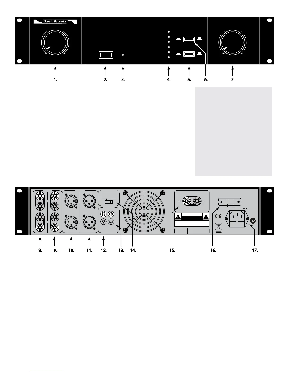
REAR PANEL
8. HIGH LEVEL INPUT – Speaker level inputs are provided to
allow interface with sources that do not provide a line level
subwoofer output.
9. HIGH LEVEL OUTPUT - Speaker level pass-through outputs
connect directly to speakers.
10. BALANCED LINE INPUT – Connect to balance line signal
source. (Pin 1 GND, Pin 2 +, Pin 3 -)
11. BALANCED LINE OUTPUT - Convenience output for
connection to other balance line equipment.
12. LINE LEVEL INPUT - Connect to line level output (RCA
connector) of receiver or pre-amplier.
13. LINE LEVEL OUTPUT – Convenience output for connection
to other line level equipment.
14. NO SIGNAL MUTE SWITCH – This is a 2 position slide
switch. In the far left (ON) position, the amplier is in a
powered up mode. The power LED on the front panel will
glow blue. In the right (AUTO) position, the amplier will
monitor signal input and power up automatically when signal
is received. The LED on the front will glow red until it senses
an audio signal, then blue when it is activated. In this mode
the amplier will power down automatically after 10 to 20
minutes with no audio activity.
15. AMPLIFIER OUTPUT - Binding posts provide output to
subwoofer(s). (Minimum 4 ohm load.)
16. INPUT VOLTAGE SWITCH - Select between 115 volts AC
/60Hz (USA) and 230 volts AC/50Hz (European).
17. POWER SOCKET – AC Power cord plugs into this socket.
Appropriate IEC power cord is provided.
FRONT PANEL
1. CROSSOVER FREQUENCY CONTROL – The crossover frequency is variable from
(far left) 50 Hz to 100 Hz (far right).
2. POWER – Push on, push off
3. WORKING STATUS LED – When the power is on, the LED lights red. When power
is rst turned on the amplier enters a self-check mode followed by a standby mode.
When audio signal is detected the amplier automatically turns on and the LED turns
blue. When amplier the is in the protection mode the LED will show red.
4. OUTPUT SIGNAL LEVEL LED’S - As output increases the LED’s will light from the
bottom up. Top LED indicates clipping.
5. PHASE CONTROL – Push on, push off. Will reverse phase of output 180 degrees.
6. LOW PASS FILTER – The in position will turn off the low pass lter allowing the
amplier to run full bandwidth.
7. VOLUME CONTROL – Clockwise increase, counter clockwise decrease.
Some words of caution:
• Do not attempt to service this
product yourself, as opening or
removing the cover may expose
you to dangerous voltage or
other hazards.
• Do not block intake (bottom front)
or exhaust (rear) vents.
• Do not cycle power switch on
front panel on and off quickly and
repeatedly. Allow 5 seconds for
amplier to complete it’s startup
routine.
 Loading...