EasyManua.ls Logo

Steel City 55210 User Manual

Steel City 55210
36 pages
To Next Page IconTo Next Page
Page #1 background imageLoading...
Page #1 background image
User Manual
Read and understand this manual before using machine.
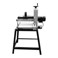
16-32 DRUM SANDER
STEEL CITY TOOL WORKS Manual Part No. OR72303
CUS
®
Model No.
55210

Questions and Answers:

Steel City 55210 Specifications

General IconGeneral
BrandSteel City
Model55210
CategorySander
LanguageEnglish

Summary

INTRODUCTION

WARRANTY

PRODUCT SPECIFICATIONS

Motor and Product Specifications

Details drum and belt motor specs, plus key operational parameters like sanding width and feed rate.

Shipping Dimensions

Information on the carton type, length, width, height, and gross weight for shipping.

Accessories Information

Information on available accessories and how to find more details.

FEATURE IDENTIFICATION

Key Machine Components

Identifies major parts of the drum sander using lettered labels from A to J.

GENERAL SAFETY

WARNING: TO AVOID serious injury and damage...

General warning to read and follow all safety and operating instructions before use.

WARNING: Exposure to dust...

Information on health risks from dust and precautions to take.

WARNING: ALWAYS wear eye protection...

Emphasizes the critical need for eye protection during operation.

GENERAL SAFETY GUIDELINES

Critical Safety Warnings

Covers essential warnings like hearing protection, dust masks, work area safety, and electrical precautions.

Operational Safety Rules

Outlines rules for safe machine operation, including guards, balance, and alertness.

Prohibited Actions

Lists actions to avoid, such as standing on the machine or leaving it unattended.

PRODUCT SAFETY

Serious personal injury may occur...

Highlights risks from overlooking safety or lack of familiarity.

Every work area is different...

Advises caution and respect for the machine in any work area.

Prevent electrical shock...

Mandates adherence to electrical codes and qualified personnel for wiring.

WARNING: TO REDUCE the risk of electrical shock...

Prohibits outdoor use and exposure to rain/moisture.

STOP using this machine...

Advises immediate cessation of use if difficulties arise.

Safety decals are on this machine...

Stresses the importance of maintaining legible safety decals.

DO NOT leave the unit plugged into the electrical outlet.

Instruction to unplug the unit when not in use or for servicing.

DO NOT handle the plug or drum sander with wet hands.

Warning against handling electrical components with wet hands.

DO NOT use the drum sander as a toy.

Prohibits using the sander as a toy or near children.

OPERATIONS

Drum Height and Speed Control

Explains adjusting drum height via handwheel and conveyor speed via switch.

Operating Procedures and Grit Selection

Outlines basic operation steps, how to determine cut depth, and sandpaper grit choices.

Dust Collection Requirements

Details the dust port and the necessity of using a dust collection system.

ELECTRICAL REQUIREMENTS

Electrical Safety and Wiring

Emphasizes adherence to codes, using qualified personnel, and avoiding outdoor use.

Power Connection Procedure

Instructions on when to connect the machine to the power source.

GROUNDING INSTRUCTIONS

WARNING: This machine MUST BE GROUNDED...

Stresses the critical importance of grounding for operator safety.

IMPROPER ELECTRICAL CONNECTION...

Explains risks of improper grounding conductor connection.

PLUGS/RECEPTACLES

Details plug and receptacle requirements and adapter usage.

EXTENSION CORDS

WARNING: To reduce the risk of fire or electrical shock...

Warns about using the proper gauge extension cord.

CAUTION: USE ONLY a 3-wire extension cord...

Specifies requirements for extension cords, including grounding and outdoor use.

MINIMUM RECOMMENDED GAUGE FOR EXTENSION CORDS (AWG)

Provides a table of recommended wire gauges for extension cords based on amperage and length.

UNPACKING & INVENTORY

Handling and Inspection

Advises on safe lifting, checking for damage, and removing protective coatings.

Part Verification

Instructs users to verify all parts are present before operation and how to report missing items.

Fig. A: Initial Parts

Diagram showing initial parts like shims, wrenches, and handwheel.

UNPACKING & INVENTORY DETAILS

Fig. B: Stand Components

Diagram showing stand components like legs and horizontal supports.

Fig. C: Leveling Feet and Hardware

Diagram showing leveling feet, nuts, and washers.

UNPACKING & INVENTORY COMPONENTS

Fig. D: Assembly Hardware

Diagram showing various screws, nuts, and washers for assembly.

ASSEMBLY

Stand and Handwheel Assembly

Instructions for assembling the stand structure and attaching the handle to the handwheel.

Mounting Handwheel Assembly

Steps for mounting the assembled handwheel onto the height adjustment shaft.

ASSEMBLY PROCEDURES

Mounting Sander and Stabilizer Bracket

Instructions for securing the sander to the stand and attaching the stabilizer bracket.

Installing Abrasive Strips

Guidance on installing abrasive strips, noting it should be done after adjustments.

ASSEMBLY DETAILS

Fig. 4B: Wrapping Abrasive Strip

Illustration showing wrapping the abrasive strip around the drum.

Fig. 4C: Tensioner Clip Mechanism

Illustration showing the spring loaded shaft and tensioner clip mechanism.

Fig. 4D: Tensioner Clip Close-up

Close-up view of the spring loaded shaft and tensioner clip.

ADJUSTMENTS

Sanding Drum Alignment

Procedure for aligning the sanding drum parallel to the table.

Safety Warning for Adjustments

Critical safety warning to disconnect power before performing adjustments.

Adjustment Diagrams

Diagrams illustrating elevation tension screws, measurements, and mounting bolts.

ADJUSTMENT PROCEDURES

Drum Assembly Pivoting

Instructions for loosening bolts to allow the drum assembly to pivot for alignment.

Conveyor Belt Tracking

Instructions for adjusting the conveyor belt tracking.

ADJUSTMENT DETAILS

Fig. 12: Tracking Screw Adjustment

Illustration of adjusting the tracking screw using a wrench.

SANDER OPERATIONS

Drum Height and Speed Control

Explains adjusting drum height via handwheel and conveyor speed via switch.

Operating Procedures and Grit Selection

Outlines basic operation steps, how to determine cut depth, and sandpaper grit choices.

Dust Collection Requirements

Details the dust port and the necessity of using a dust collection system.

MAINTENANCE

Lubrication and Belt Replacement

Instructions for lubricating moving parts and replacing the conveyor feed belt.

Maintenance Safety Warning

Critical safety warning to disconnect power before performing maintenance.

Maintenance Diagrams

Diagrams illustrating screws and mounting bolts related to maintenance.

TROUBLESHOOTING GUIDE

Abrasive strip issues

Problem and solution for abrasive strips coming loose from clips.

Wood burning during sanding

Problem and solution for wood burning during the sanding process.

Intermittent feed belt operation

Problem and solution for the sanding drum feed belt running intermittently.

Feed belt slipping on rollers

Problem and solution for the sanding drum feed belt slipping on drive rollers.

Stock slipping on feed belt

Problem and solution for workpieces slipping on the sanding drum feed belt.

Uneven ripples on stock

Problem and solution for non-evenly spaced ripples on the sanded surface.

Evenly spaced ripples on stock

Problem and solution for evenly spaced ripples on the sanded surface.

Motor overload or breaker trips

Problem and solution for motor overload trips or shop wiring circuit breaker trips.

PARTS LIST AND DIAGRAMS

Main Assembly Parts Diagram

Visual representation of main replaceable parts with numerical identifiers.

PARTS LIST AND DIAGRAMS (Main Details)

Main Assembly Part Number and Description List

Comprehensive list of part numbers, descriptions, and quantities for the machine.

PARTS LIST AND DIAGRAMS (Motor)

Motor Assembly Parts Diagram

Exploded view of the motor and related components with numerical identifiers.

PARTS LIST AND DIAGRAMS (Motor Details)

Motor Assembly Part Number and Description List

List of part numbers and descriptions for motor assembly components.

PARTS LIST AND DIAGRAMS (Control Box)

Control Box and Feed System Parts Diagram

Exploded view of control box, feed rollers, and related parts with identifiers.

PARTS LIST AND DIAGRAMS (Control Box Details)

Control Box and Feed System Part Number and Description List

List of part numbers and descriptions for control box and feed system components.

PARTS LIST AND DIAGRAMS (Stand)

Stand Components Parts Diagram and List

Exploded view and list of parts related to the stand assembly.

Related product manuals