22
PREPARING THE TELESCOPING POLES
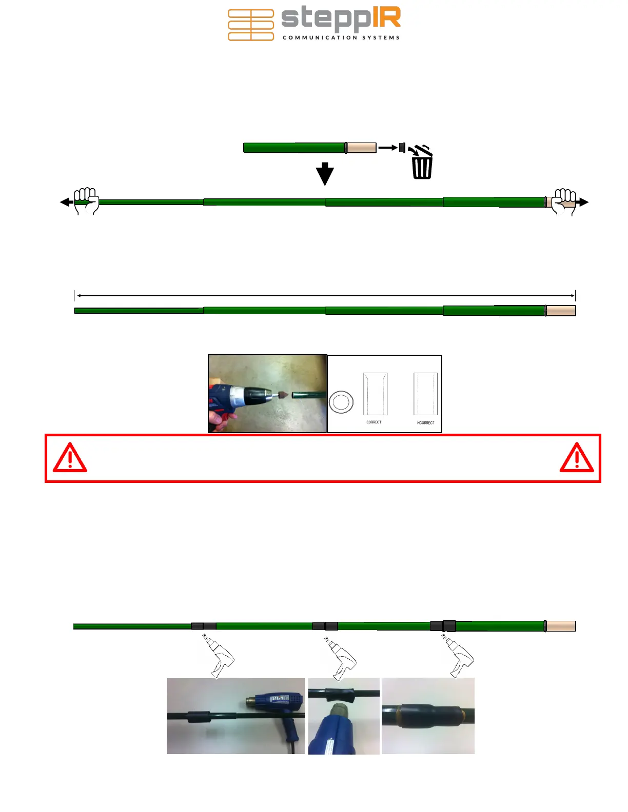
1. Extend the telescoping poles (PN 10-1013-02) to full length by firmly locking each section of the pole in place. A good
methodology is to position each half of the joint so that they are several inches apart (while still within each other), and
then pull quickly and firmly. Do this for each pole. There are rubber plugs inside the base section of each telescoping
pole. These make it easier for handling, but they MUST BE REMOVED BEFORE ASSEMBLY. VERIFY THE FOAM IN-
SERT IN THE PLUG HAS NOT MADE ITS WAY DOWN THE POLE AND THAT THERE IS NO OTHER FOREIGN DE-
BRIS INSIDE THE POLE.
2. With the poles fully extended, trim the end of the tip element of each pole so that the pole is 212.75 inches (540.4 cm)
from the tip of the pole to the butt end, as shown below. ONLY trim the poles used for the 40/30 loops—if your antenna
has 20m-6m straight elements, those should not be trimmed (must have a length of at least 213.1”). Use a hack saw,
pipe cutter, or similar cutting blade that is suitable for fiberglass. Be sure that you cut the pole perpendicular to the length
of the pole so that it is as “square” as possible.
3. Using the conical drill bit, chamfer the tips of the 40/30 poles as shown below. The image below shows the proper
angle to chamfer to. Clean out the interior of the fiberglass poles after chamfering it.
4. Each telescoping pole uses 3 polyolefin heat shrink pieces 1.5” x 3” (PN 10-1059-01), one covering each joint after it
has been pulled tight. Once finished, the seal is secure and waterproof. This product requires a heat gun for activation
of the adhesive.
5. When positioning the heat shrink, place it so that the joint of the telescoping pole is centered in the middle of the heat
shrink.
6. Using a heat gun (hair dryers will NOT work), apply heat evenly around the entire area of heat shrink. Note: there are
4 blue colored lines imprinted on the tubing. The joint is considered done being heated and waterproof when the lines
change color to a yellowish green. Each line needs to change color to ensure even adhesion temperatures.
7. The heat shrink will want to slide as it is heated so wear gloves and reposition the heat shrink to keep it centered on
the joint as needed. Caution: The heat shrink will be HOT, wear insulated gloves!
212.75” (540.4 cm)
LOOK INSIDE OF THE TELESCOPING POLE TO VERIFY NOTHING IS BLOCKING IT. YOU
SHOULD BE ABLE TO SEE LIGHT AT THE OTHER END IF THE POLE IS KEPT STRAIGHT.
DEBRIS INSIDE THE TELESCOPING POLES CAN LEAD TO FAILURE OF THE EHU.
 Loading...


