The Steren K-920 Electronic Elevator Kit is a DIY project designed for assembling a miniature electronic elevator. This manual provides detailed instructions for constructing the elevator, from assembling the chassis to wiring the electronic components and operating the finished device.
Function Description:
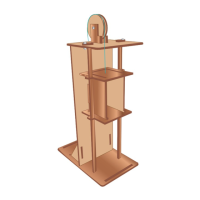
The K-920 Electronic Elevator Kit allows users to build a functional model elevator. Once assembled, the elevator cab can be controlled to move up and down using two push-type buttons. The kit is intended as an educational tool, providing hands-on experience with basic electronics, mechanical assembly, and the principles of elevator operation. It's designed to be a fun and engaging project for individuals interested in STEM fields, particularly electronics and engineering. The elevator operates by a gearmotor that drives a pulley system, which in turn moves the elevator cab along a set of guides.
Important Technical Specifications:
- Model Number: K-920
- Kit Identifier: 0618A
- Manual Version: V0.0
- Power Input: 9V (square battery)
- Electronic Components:
- Transistors: 2N2222 (4 pieces)
- Resistors: 560 Ω (green, blue, coffee) (4 pieces)
- Resistors: 3K9 (orange, white, red) (2 pieces)
- Diodes: 1N4148 (4 pieces)
- LEDs: Red (2 pieces)
- Buttons: Push-type (2 pieces)
- Motor: Gearmotor (1 piece)
- Connectors: Header (1 piece), Stack brooch (1 piece)
- Cables: Dupont cable (1 piece)
- Chassis Components (Wood/MDF pieces):
- A: 1 piece (base/top plate)
- B: 1 piece (back panel)
- C: 2 pieces (support beams)
- D: 2 pieces (cab floor/ceiling)
- E: 2 pieces (cab side panels)
- F: 1 piece (cab back panel)
- G: 2 pieces (guides)
- H: 2 pieces (motor mounts)
- I: 1 piece (pulley support)
- J: 2 pieces (side supports)
- K: 2 pieces (pulley side panels)
- L: 2 pieces (pulley wheels, 4.7 cm diameter)
- M: 1 piece (top plate)
- N: 2 pieces (pulley spacers, 1.7 cm diameter)
- Ñ: 1 piece (pulley spacer, 1.5 cm diameter)
- O: 1 piece (thread anchor, 1.2 cm diameter)
- Fasteners:
- P: 2 pieces (safety nuts)
- Q: 1 piece (safety nut)
- S: 8 pieces (nuts)
- T: 3 pieces (large screws)
- U: 6 pieces (small screws)
- Other Materials:
- V: Nylon thread (1 piece)
Usage Features:
The elevator is operated via two push-type buttons (S1 and S2) located on the PCB.
- Ascending: Press and hold the left button (S1) to make the elevator car go up.
- Descending: Press and hold the right button (S2) to make the elevator car go down.
The design incorporates a pulley system driven by a gearmotor, which is connected to the elevator cab via a nylon thread. The thread is carefully routed through the cab and over the pulley to facilitate vertical movement. The kit emphasizes careful assembly to ensure smooth operation, particularly regarding the pulley system and the movement of the cab along the guides.
Maintenance Features:
The manual highlights several important considerations for assembly and potential maintenance:
- Careful Handling: All chassis parts are made of materials that can break easily, requiring careful handling during assembly.
- Adhesive Use: Wood glue is recommended for fixing the joints of the assembly, but it's crucial to avoid applying glue to moving parts to ensure proper functionality.
- Screw Tightening: Screws should not be overtightened to prevent damage to the parts. Specifically, the nut on the pulley assembly (step 9) should not be tightened too much, as the pulley needs to rotate freely for the elevator to move.
- Polarity Awareness: When connecting electronic components, especially the motor and battery, attention to polarity is essential to prevent damage and ensure correct operation. The manual explicitly warns about this for the Dupont cable connection to the motor and the battery connection to the brooch.
- Tools Needed: The assembly requires common household tools: a flat screwdriver, a cross screwdriver, wood glue, and tip tweezers. These tools are not included in the kit and must be provided by the user.
- Supervision for Children: The device is not intended for unsupervised use by individuals with reduced physical, sensory, or mental capabilities, or lack of experience/knowledge, including children. Children should be supervised to ensure they do not use the device as a toy. This implies that while it's an educational kit, adult guidance is important during assembly and initial use.
- Troubleshooting (Implied): Although not explicitly detailed as "maintenance," the instructions for careful assembly, correct component placement, and attention to polarity serve as preventative measures against common issues. If the elevator does not function correctly, users would likely need to re-check these assembly steps, particularly the wiring and the freedom of movement of the mechanical parts. The modular nature of the kit, with separate chassis and PCB assembly, allows for easier isolation of issues if they arise.