This unit assumes a common neg between all battery banks and alts. The unit is designed so that the is to prevent any short circuit when running the new cables, a short circuit on a battery can
alternator and starter battery are in contact when the engine is off, this is to ensure that when the easily cause a fire or the battery in question could explode. If in doubt please employ a
engine starts up if you have an alternator which needs a voltage on the alternator to fire it up then professional electrician to install the unit. Or contact Sterling power products on help@sterling-
the starter battery connection will supply that voltage. When the engine is started and the alternator power.com or see our web site www.sterling-power.com
fires up the system maintains the connection with the starter battery until this battery exceeds about Always work from the unit to the battery bank. ie fit the cables onto the unit then the fuse then
13.3 volts ( ), this could be a few mins or a few secs. The system then checks battery connect them to the battery as this way its much safer than connecting cables to the batteries
bank 2 to ensure that it is ok and does not have a short circuit on it, it then engages battery bank 2 then connecting to the unit.
and keeps the starter battery and battery bank 2 on line until they both reach 13.3 volts, ( again this it is recommended to place fuses as close to the batteries as possible, also fit them first as
could take a few mins or a few secs depending on the state and size of the battery bank ) the system they can protect against any accidents during installation. The fuses are there to protect the
then checks battery bank 3 ( in a 3 output unit ) and then engages battery bank three. this process cables in the event of the pos cable coming in contact with the chassis of a vehicle or a steel hull
could take as little as 3 seconds under normal conditions or in extreme cases with large flat batteries on a narrow boat or a bonding system on a boat or vehicle. In some case this is a statuary
up to an hour or so. The unit continues to monitor the voltages on the 3 outputs and the alternator requirement.
input, in theory these should all be the same, any attempt to pull these voltages below 13 volts Fuses are not supplied with the unit but can be purchased separate from your local chandlery or
means that one battery bank is attempting to discharge in excess of the ability of the alternator to from Sterling Power Products. For high current fuses Sterling always recommends fuses to be
supply the current and is going of start taking power from one of its neighbouring battery banks, in installed at about 50% larger than the maximum possible current, round this figure up to the
the event of this happening the system will channel the alternator power into the battery bank nearest 50 amps.
which requires this load, and disconnect and protect the other battery banks.
I would advise you read what all the alarm functions do , this may make understanding the
system easier.
To install the unit, pick a cool part of the engine room ( ie as low as possible ) the unit is to . It
also does not matter what way up the unit goes. however the unit has been designed so the
Please note that the unit will not switch off as soon as you switch off the engine, cables do not run across the bolts from other battery banks, if the unit is connected as per the
when the engine is switched off the battery banks will be isolated but the unit l.e.d.s will remain on obvious writing on the unit and the cables should be brought up from below. You can connect
for about 10 secs or so. the unit at any angle you wish to assist in the wiring process. Using the 4 fixing holes firmly
A special connection is secure to a bulkhead. when all cables are connected tie and secure the cables in such a way as
available on the unit for advanced regs and remote sensors on alternators with battery sensed regs ( there wright is supported on the bulkhead and they do not vibrate or touch any of the other
volvo ), we strongly recommend you use this point, this is to ensure the maximum performance of studs.
the alternator and compensates for any voltage drop between the alt and this control box . Ensure your alternator or alternators are working with in the total limits of the unit , ie is the
unit is 180 amps the total maximum current is 180 amps, it does not matter if this is a 50 amp
1 ) under normal running alt plus and 70 amp alt as the total possible current does not exceed the continuous rating . For
conditions with the alternator working then all these l.e.d.s should be on, these l.e.d.s show that a twin alt input, each output can deal with the total from both alts output together . ie a twin
circuit is active. In the event of one l.e.d. being off then look below on the red trip warning l.e.d.s 130 alt unit can handle the full charge of 260 amps out any of the outputs.
to find out why that circuit has been disconnected. Fit in a position to minimize the length of cables used, the shorter the cables the better. Look at
2 ) in the event of the alternator voltage exceeding the cable chart below for recommended cable size, larger cables are usually hard to come by so
16 volts (x 2 for 24 v system ) , the unit will disconnect all battery banks from the batteries ( all if for example you want 200 amp cable, but only have 50 amp cable then simple run 4 lengths
the blue l.e.d.s showing connection to each battery bank will be off and this alarm l.e.d. will be of 50 amp cable as all you are doing is running is copper.
flashing) this will protect the batteries from excessive damage and allow you to continue on your Try to connect where possible the engine starter battery to the battery terminal marked starter,
journey without the worry of exploding batteries and have the alternator regulator repaired at your this connection is recommenced but not the end of the world if not possible. There is no life
next destination: in the event of the alternator voltage dropping down to below 15 v for what ever threatening danger involved if this is not used on the starter battery , the only reason for this is
reason ( ie if the advanced reg was a Sterling and it also picked up the high voltage fault, the we take a special feed from this engine start battery to ensure the alternator will ''fire up '' so
advanced reg would return the alternator regulator control back to the original reg which may be we want to ensure there is life in this battery in order to fire up the alternator, our design
ok.) during the journey then the unit would reset and continue to charge the battery banks . assumption is if this battery is dead you cannot start the engine so the unit would not work
2 this is where 16 volts ( 32 volts ) is sensed on one anyway, however if the battery is dead and you jump start the engine then we will have the
of the battery bank inputs, this could come from something for example a defective battery charger power required to fire up the engine alternator so all the batteries can then be recharged.
on battery bank 3 trying to back feed the dangerous voltage back into the other battery banks. The Failure to have any power in this battery bank might prevent your alternator from firing up and
unit will identify the offending battery bank and isolate battery bank to prevent damage to the rest so the unit might not work correctly( not that it would matter anyway if the alternator is not
of the system ( this will result in any damage which might be caused by the defective bank being working ) .
limited to that bank and not causing damage to the other battery banks) however we are unable to Negative connection. the negative connection is simply a feed for the internal electronics, this
prevent the damage being caused tho the actual battery bank causing the problem. for this look at actual current in this cable would not exceed 2 amps , so a normal 5-10 amp cable would be
our new range of voltage sensitive current limiting relays. more than enough for this connection. the negative should go to a negative on the main battery
3 ) this is where there has been an attempt by one battery bank to bank common neg or any other good local neg source.
discharge the others, for example if there was a high power inverter ( 3000 watts ) on the domestic this is a d/c feed from a ignition source, ie from the d+ / 61/ L/ on the back of an
battery bank and the battery was very low, if someone for example put on the kettle then the alternator or a feed direct from the ignition key switch. or anything which becomes live when
inverter would attempt to pull 200 amps from the other battery banks, in this event the unit would the engine is working and is off when the engine stops. this simply tells the unit that the engine
sense this and ensure the other battery banks would be disengaged and the alternator path directed is on or off.
to the inverter bank only, until such time as the high load was discontinued and the battery bank When the engine is started then the ignition feed
allowed to come up to 13.3 volts, then the other banks would come back on line and the batteries should become live activating the unit, expect to see at least 1 l.e.d. come on. The unit then goes
charger accordingly as per the explained start up sequence. If the engine battery safety voltage limit through a test sequence , checking each battery bank to see if everything is o.k.. Then the unit
was reached this would disconnect all batteries and direct the power to the engine start starts with the engine start battery and charges it until it exceeds 13.3 volts, this could take 10
4 ) , if this l.e.d. is flashing then the alternator ( or battery charger )is secs or 10 mins. it will then switch on battery bank 2 together with the starter battery and start
below 13.3 volts ( 26.6v for 24 v etc), this is usual and would only happen if the cable between the to charge it until both reach at least 13.3 v , then battery bank 3 will be connected. With all
alt and the unit is to thin or to long for the amount of current , or there is a high drain from one outputs now working the system will continue to charge all battery banks (in normal
battery bank. If l.e.d. off alt below 10 volts ( which means its not working. If L.E.D.is on solid then circumstances this would be all the unit needed to do)
voltage over 13.3 and working ok The system continues to monitor all outputs and inputs. In the event of any attempt to reverse
5 ) l.e.d. on means the unit is working normally, flashing Blue l.e.d. means feed from one battery battery bank, the bank which is attempting the reverse feed (the one with
that the alternator is off ( or not working ) . The unit is in stand by mode. the heaviest load, ie an anchor winch or a large inverter could have been turned on) will be kept
6 ) negative stud, This is the device control negative , a simple 10 amp cable is more than enough to on line with the alternator in order to supply the max current to this demand source and the
run the device, this must be connected to the common negative of the batteries other battery banks will be isolated to prevent power loss from those battery banks, this
7 ) battery sense connection .this is where we recommend that you place the remote sense wire isolation will remain until such time as the battery bank in question has come up to about 13.3
from an Advanced alternator regulator or a battery sensed alternator, it ensures that the regulator is volts ( or the priority engine start battery falls below 12.4 v )before engaging the rest of the
always charging all battery banks the same and prevents any over charge of any batteries, if there is battery banks . When the engine is switched off the unit shuts down after 10 seconds . and uses
no advanced reg or battery sensed reg being used with the alternator then do not worry about this no power.
connection. two or more alternator can be connected to the alternator input
8) Auxiliary battery banks 2 and 3 ( on a 2 output unit there will only be one aux battery bank ) position, this can either be 2 alts from one engine or 2 alts on different engines .
these connect to the battery banks other than the starter battery of the engine which the alternator is . This is a special design for most motor
connected to. boats fitted with a twin engines ( ie twin merc , volvo, yanmar ) they tend to come with about
9 ) Alternator input. this is the main alternator input cable, it could also be used for a battery 110 amp alts fitted to each engine . in conventional boat installations a lot of potential power
charger , or the output of an alternator to battery charger etc to increase the number of battery banks from these alternators are not effectively unitized , with power being wasted , with each
you wish to charge. alternator charging a limited number of the total banks on the vessel and not effectively
10 ) This connection is recommenced to be used by the engine starter battery. there is no life channeling power from both alternators to where the max power is required .
threatening danger involved if this is not used on the starter battery , the only reason for this is that this unit can used for lots of other functions due to its 0.0 volt drop across it , it can
the design takes a special feed from this engine start battery to ensure the alternator will ''fire up '' split the outputs from any power source and distribute this power to different battery banks , ie
so we want to ensure there is life in this battery in order to fire up the alternator, our design you may have one of
assumption is if this battery is dead you cannot start the engine so the unit would not work anyway, our battery to battery chargers ( which have a single output ) or a alternator to battery charger (
however if the battery is dead and you jump start the engine then we will have the power required again with a single boosted output ) and you wish to charge more than one battery bank, then
to fire up this unit and the engine alternator so all the batteries can re charge. Failure to have any simply connect the power to the alt position and the unit will split accordingly.
power in this battery bank ( ie a flat battery, the alternator may not ''fire up''.) : Obviously under normal running functions there should be no alarms,
11 ) ignition feed: connect direct to an ignition feed or to the back of the alternator to the D+/61/L however things do go wrong, with any safety system there is always got to be a balance
terminal, ie any feed which becomes live when the engine is running and goes off when it stops. between safety and the safety system causing more problems than it protects, with some alarms
this simply informs the unit the engine should be working and to start this is obvious the safety alarm switches everything off and thats that, however safety functions
such as engine priority system which ensures the engine start battery is ok is a bit more complex
. This alarm function has a timer involved which increases every time the alarm is engaged in
each session , ie the first alarm locks the engine battery on line for 1 min then it resets to feed
the other batteries, if the alarm happens again then the time is increased to 2 mins on the
engine start battery, then if the other batteries come back on line, if the alarm happens again the
time is then 3 mins etc etc. if this alarm happens alot then the bottom line is you alternator
system is not capable of keeping up with your demand and should be up rated or an extra alt
The actual installation of this device is very straight forward, the instructions are shown with a 1 in fitted. the Pro Split has no magic solution for the other than ensure the starting of your engine.
3 out 180 amp unit and a 2 alt in 4 battery bank out. However a 2 output unit only has 2 outputs
but connects up the same with the obvious 1 less output.
Before starting this installation, disconnect the negative and positive cables from the batteries, this
x 2 for 24 v
Fuses.
It will however
continue to monitor the starter battery as the most important bank and in the event, at any stage of
the starter battery dropping below 12.6 volts ( x 2 for 24v ) then all battery banks will be
disengaged and all power be diverted into the starter battery bank until it comes up to 13.3 voltage.
then it will repeat the start up process. This would be a very unlikely situation but is a fail safe
built into the software to guarantee the engine start battery above all others
High alternator voltage trip, (red l.e.d. flashing )
) High output voltage trip. ( red l.e.d. on solid )
Back feed engaged.( red l.e.d. on )
Ignition feed:
How does the unit work, and what to expect.
Trip/Alarm sequence
Other uses for this product.
use with a single output battery charger to give multible output charger, also with wind gen, solar
cells, or use with sterling Battery to Battery charger to give extra outputs etc etc
For Maximum performance from your alternator this unit should be used in conjunction with a
Installation:
Always remember that if you wish to boost the performance of your system , look at the
Sterling Advanced alternator regulators or the battery to battery chargers
Sterling Power Products has a full range of high current fuses from 100-500
amps, the part number is GANLR for the fuse holder and GANL100 for a 100 amp fuse and
GANL200 for a 200 amp fuse etc
Unit switching off.
Advanced alternator regulators or alternators with battery sense regulators.
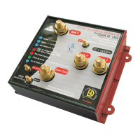
L.E.D. information on the front of the unit
Starter battery / battery 2, battery 3,starter 2, on line .( blue l.e.d.s )
On ok ( l.e.d. Blue on )
Twin alternator installation:
Other uses.
Sterling Advanced Digital Alternator regulator/ Alternator to battery charger/ Battery to battery
charger
Alternator power rail state
Twin engine, twin alternator , isolated ,4 output unit
ProSplit R - Functions + Installation
 Loading...