What do I expect to see from this unit and why?
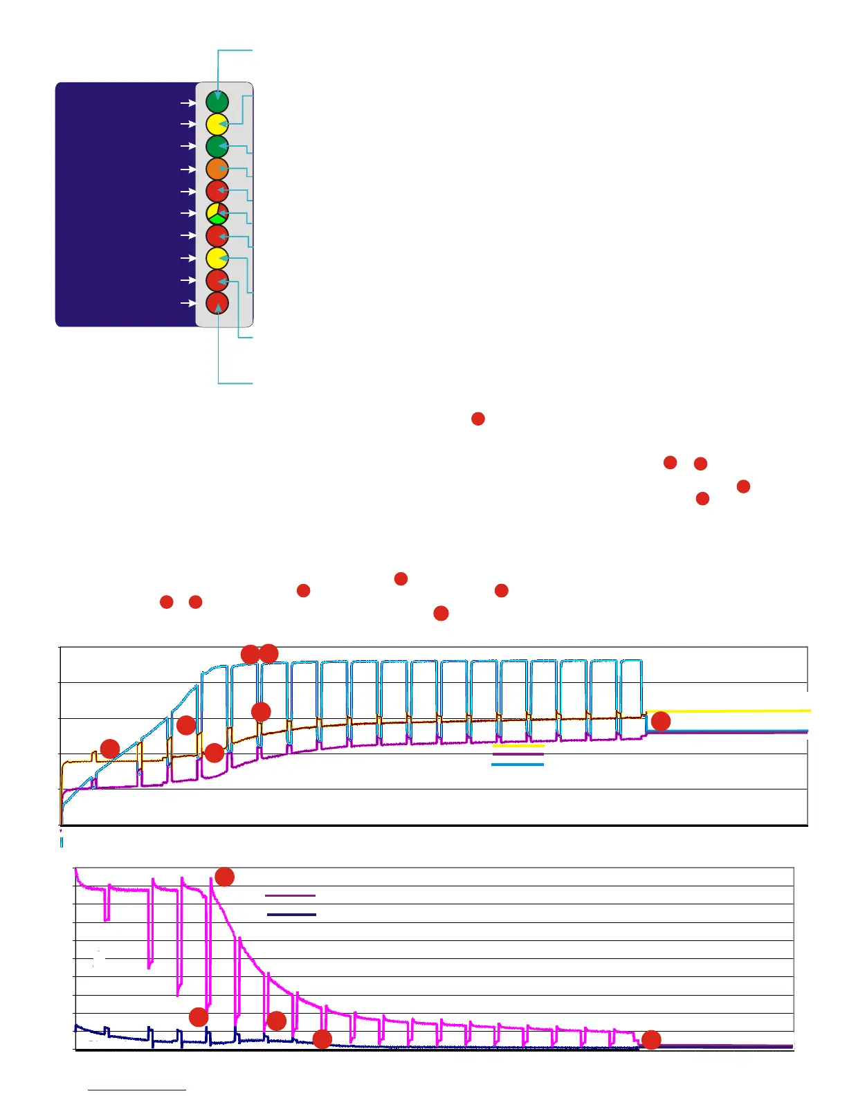
The current graph
System voltage graph
Position : The interesting point here is that this is the magic point, the point where
The below test was set up and monitored and is as close as possible as to what happens the domestic battery voltage exceeds the alternator input voltage. This is what the
on the average split charger system, the engine battery is a 100 amp hr standard lead process is all about.
acid, and the domestic battery is 3 x 100 amp hr standard lead acid. The engine battery The steps on the graphs show the unit boosting every 15 minutes, then resting for 2.5
was discharger to 11 volts ( about 10 engine starts ) and the domestic bank to about 11 minutes. An example of this is the time period between and .What you can see
volts ( will no longer run an inverter and is about 60% empty . The alternator used is a here is that by switching off the amplifier (to help the engine battery charger more),
Bosch 90 amp with a standard 13.9 volt ( variable ) regulator. the unit battery type is the engine battery voltage curve increases during that step shown at point which
programmed to open lead acid. results in extra current going into the engine battery at position . The current
There are 2 x graphs , one is the current into the batteries, and the other is various reflection of this process is reflected in the other graph marked ‘the current graph’.
voltages on the system shows the current flow into the engine start battery and the domestic
: system. The effect of the amplifier can be clearly seen when the unit switches off for its
The key points to pick up on here are: 2.5 minutes rest cycle. The current drops from position = 95 amps to position =
The yellow trace (alternator voltage into the unit) clearly shows that the system is about 30 amps, a 300% difference. At the same time you can see extra going into the
doing its job. It is designed to pull this voltage down a little to enable the standard starter battery which clearly charges through the whole exercise.
alternator regulator to produce its full current. You can clearly see that on position on On completion the unit switches off, and the process continues as a conventional split
the voltage curve the voltage is pulled down to position . The result in current change charger system , if however the domestic battery falls below 12 volts, the system
is from position - which is about 70 amps improvement and a good will auto restart and continue the process again.
increase in current. Shows that the engine battery is full and taking no more current.
CONSTANT CURRENT
slow flash unit in-active
TIMER ACTIVATED
FLOAT/CONSTANT V
LOW BATTERY VOLTS
HIGH BATTERY TRIP/V
BATTERY TYPE
HIGH ALT VOLTAGE TRIP
HIGH ALT TEMP DISENG
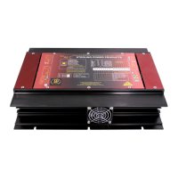
HEAT SINK R.H.SIDE
HEAT SINK L.H.SIDE
Green High Charge Rate On: (top L.E.D. 1) This should be on from start-up (slow flash shows unit is on, but on rest mode, for
the first 2.5 mins on start-up and every 20 minutes or so thereafter, see graph ) and shows that the alternator should be
working at its maximum. It should remain on until the green float comes on and this shows that the high charge rate is
complete.
Yellow Timer Activated: This comes on when the voltage reaches about 13.9 - 14 volts (x 2 for 24 v), and depending on how
long it took to come on, will dictate how long the timing cycle will remain on. The software will calculate the timing for the
high charge rate. This will vary from 1 - 6 hours and the time will be displayed on the remote panel and a count down . This
light will remain on until the high charge rate is over, and will go out at the same time as the high charge rate between 1-6
hrs after activation.
Green Float Mode: This indicates that all the high charge cycles are now over and should remain on after all the high charge
lights are out. The system is now running at a standard charge rate only (about 14 volts) regulated on the battery.
Orange Low Voltage Warning: This is simply says that there is a low voltage at the main battery bank and has no active
function. For information only; usually indicates a defective alternator.
Red Dual Information L.E.D: This L.E.D. Has two functions and as such has two display modes. flashing = high temp trip and
l.e.d. on permanent = high battery voltage trip
Tri Coloured L.E.D: This simply displays the battery type that the processor has been set to. This is a tri-coloured l.e.d.
Yellow = open lead acid, Green = gel /sealed lead acid . Red = A.G.M..
Red High Alternator voltage trip: This will warn you and switch off the boost section. This means that your alternator’s own
regulator has failed and that the alternator will now boil and destroy your batteries. There is simply nothing we can do about
this, except warn you. and stop your engine as soon as possible. Remove the
alternator input cable, then continue your journey and have the alternator repaired.
Yellow: System disengaged, this refers to the boost section being deactivated for the following reasons: The alternator
temperature sensor has exceeded 90 deg c and has automatically disengaged the unit to allow the alternator to cool down,
there is a high temp on the heat sink, or there is a high temperature on the battery temp sensor. It will reset once the safety
parameter that caused the problem has been reduced.
Red : This gives a simple warning that the product is overheating. In this case the boost section will switch off and should
reduce the problem. However, we cannot prevent the unit continuing to overheat if it has been placed in a bad place such as
a sealed box with no ventilation. If this high temperature is not addressed by increasing the cooling effect , ie by moving the
unit to a cooler place, then it could result in the failure of the unit.
Red: same as above:
Please take this warning very seriously
2
1
4
6
7
3
12.50
13.00
13.50
14.00
14.50
15.00
9
18
28
37
46
55
64
73
83
92
101
110
119
128
138
147
156
165
174
183
193
202
211
220
229
238
248
257
266
275
284
293
303
312
321
330
339
348
358
367
376
385
394
403
413
422
431
440
449
458
468
477
486
495
504
513
523
532
541
550
559
568
578
587
596
TIME min.
Volts
alternator input voltage
starter battery voltage
domestic battery voltage
0.000
0.010
0.020
0.030
0.040
0.050
0.060
0.070
0.080
0.090
0.100
1
16
31
46
61
76
91
106
121
136
151
166
181
196
211
226
241
256
271
286
301
316
331
346
361
376
391
406
421
436
451
466
481
496
511
526
541
556
571
586
Time min.
Amps
100
90
80
70
60
50
40
30
20
10
0
time in mins
time in mins
volts
amps
domestic battery current
starter battery bank current
Domestic battery bank current curve, with engine battery bank current curve
Engine battery bank, domestic battery bank, and alternator voltage curves
4
5
8
9
5
8 9
2
3
1
6
7
10
10
L.E.D. information and alarms
Unit expectations
10
11
11
1
2
3
4
5
6
7
8
9
10
fan
fan
engine
alternator
ENSURE ALL NEGS ARE COMMON
DOMESTIC BATTERY SYSTEM
200 amp shunt
Engine
battery current
( optional remote kit )
Battery
temperature
sensor
cable
( supplied )
Remote control
and information panel
( optional remote kit )
Starter motor
solonoid
40 amp fuse
+
+
+
Full System wiring
(including optional remote kit if used )Kit parts in green
Engine
starter
key
ENGINE STARTER
BATTERY
lightlight
CE
on/offon/off
beepbeep
1
2
3
4
22
44
33
11
Power Management
with
AMP Hr Counter
Sterling power products
Amp
hr
Amps Volts
14.35 v m Pos 4
37amps 435 a/hrs
Sterling power products
CE
on/off
alarm
light
temp
System
Default
Low voltage warning
System Disengaged
System Trip
System Within Limits
Screen
Help
Bat 14.4v Timer
Alt 15.4v 134m
set up
volts
temp sensor
temp sensor
fuse
1
2
3
4
5
7
Alternator
temperature
sensor
cable
( supplied )
8
11
Advanced Digital Split Charge
Alternator Power Amplifier
Right Hand Side
Left Hand Side
10
14
1 2 3 4
This unit comes set up for the standard
200 amp shunt ( 1 mv = 1 amp ).
however it can be re-programed to
accept a 500 amp shunt 0.1 mv = 1
amp
13
a
a
b
a
b
b
ON
1 2
ON
1 2
Low alternator regulator voltage
adjustment, this should only be used
if the alternators standard voltage
regulator is set below 13.9 volts . Do
not use unless this is the case. switch,
switch 1 on, switch 2 is not in use
6
OPEN
LEAD ACID
GEL-
BATTERIES
(EXIDE SPECIFICATION)
SEALED LEAD
ACID & AGM
GEL & AGM
(USA SPECIFICATION)
ON
1 2
ON
1 2
ON
1 2
ON
1 2
LED
COLOUR
MAX. CHARGING
VOLTAGE
ABSORBTION
TIME
FLOATING
VOLTAGE
YELLOW
GREEN
GREEN-YELLOW
GREEN FLASHING
FOR 5 SEC.
14.8V / 20°C
14.4V / 20°C
14.4V / 20°C
14.1V / 20°C
13.65V / 20°C
13.8V / 20°C
13.65V / 20°C
13.5V / 20°C
1 - 3 HRS.
10 - 12 HRS.
4 - 8 HRS.
4 - 10 HRS.
ON
15
12
17
16
200 amp shunt
Domestic
battery current
( optional remote kit )
a
b
9
 Loading...