115
4.3 PREPARATION
Pool preparation: illustration
2.1
Remove dirt manually and make sure the pool and pump lter is clean. Point the discharge nozzles
downward to ensure complete cleaning coverage. Turn o the bottom drain as shown in the illustration.
Hose Assembly: illustration
2.3
&
2.4
Fit and turn each section of hose
Assemble a sucient number of hoses to reach the farthest part of the pool, then add another 1 section
of hose. Place the hose counterweight at the end of the rst section of hose, about 1 meter from the
cleaner. Place the second counterweight on top of the rst, it will need to be adjusted later.
Installation of the flow control valve: illustration
2.4
&
2.5
Connect the hose plug to the ow control valve. Attach the ow control valve to the exible adapter. The
ow control valve is used to adjust the ow rate so that the pump and the robot work properly. Turning
the valve towards the "-" reduces the robot suction ow rate, without aecting the pump's suction ow
rate.
Installation of the flow tester valve: illustration
2.4
&
2.5
Connect the female connector of the hose to the ow tester valve. Switch on the ltering system and ll
the hose with water by placing the hose in front of a discharge nozzle until it is completely lled. Stop the
pump and make sure the hose is kept submerged. The ow tester valve allows you to check the value of
the robot suction ow rate.
4.4 FIRST USE
WARNING! Read the «SAFETY INSTRUCTION» section at the
beginning of this manual including all text under subheading
therein before using this product.
Flow test: illustration
2.6
&
2.7
Before installing the robot head, test and adjust the ow rate for optimal robot operation.
Be sure to keep the hose submerged. Insert the ow control valve with the hose adapter into a pressure
nozzle (Fig. 2.6a) or into the suction system of the skimmer (Fig. 2.6b) and switch on the pump. Check
that the indicator on the tester is set to setting No. 3. To adjust the setting, turn the valve towards "+" to
increase the robot suction ow or towards "-" to decrease the robot suction ow. (Figure 2.7)
If you encounter diculties in reaching level 3 on the tester by adjusting the valve, you can try the
following solutions, depending on your installation:
• If your installation has only one suction nozzle, check that the pump of your installation has a
power between 250 and 750 W.
• If the robot is connected to a suction nozzle and a skimmer is running on your pool, reduce the
ow of the skimmer in order to increase the robot's suction ow.
• If the robot is connected to the skimmer and one or more suction nozzles are active on your
system, reduce the ow rate of the nozzles in order to increase the robot suction ow rate.
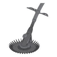
Installation of the pool cleaner: illustration
3.1
to
3.3
Once the ow rate has been adjusted, stop the pump. While keeping the hose submerged, remove the
ow tester and replace it with the robot head. Fit the anti-locking wheel on the end of the last section of
hose, about 10 cm from the robot head. The anti-locking wheel pivots on the hose to help the robot go
around steps and other obstacles in the pool.
 Loading...