PPR SET-UP (.5,1,1.5,2,2.5,3,4,5,6 PPR):
WARNING: An improper PPR setting will cause the RPM display, shift
light activation, and switch activation to be inaccurate.
1. Enter programming mode by pressing both
SCROLL
&
SELECT
buttons at the same time, and then release both buttons.
2. Scroll to the PPr parameter using the
SCROLL
button, and then
press the
SELECT
button.
3. The display will show the current setting (the default setting for a
new unit is 4 PPR).
4. Press the
SCROLL
button to change the setting.
5. Once the desired setting is displayed, press the
SELECT
button to
return to the
MAIN MENU
.
6. To exit programming mode, do not press any buttons for 5 seconds.
All changes will automatically be stored
and the unit will return to
normal operation.
TIP: When connecting to an engine with a distributor, generally, the old
rule, half the number of cylinders = PPR, still applies. When
connecting to the signal wire to a coil pack that drives 2 cylinders,
generally, the PPR = 1. When connecting to a “coil on plug” ignition
or one coil for each cylinder, the best option is to look for a tach
signal coming out of the ECU, but the .5 PPR setting may work when
directly connected to any one of the coils. If this connection is erratic
or does not function correctly, a tachometer adapter may be
required. Call technical support a 1-866-797-7223 or visit
www.SW-Performance.com for more information.
7
RPM DISPLAY ON/OFF:
1. Enter programming mode by pressing both
SCROLL
&
SELECT
buttons at the same time, and then release both buttons.
2. Scroll to the dISP parameter using the
SCROLL
button.
3. Select the dISP parameter option using the
SELECT
button.
4. The display will show the current (0n, 0FF)
”
setting (the default
setting is 0n).
5. To change the setting press the
SCROLL
button to toggle between
0n & 0FF.
6. Once the desired setting is displayed, press the
SELECT
button to
return to the
MAIN MENU
.
7. To exit programming mode, do not press any buttons for 5 seconds.
All changes will automatically store
and the unit will return to normal
operation.
8
RPM WINDOW SWITCH ACTIVATION RANGE SETUP:
TIP: If both HI and L0 values are set the same, the switched output is
disabled and will not activate. The default settings for both HI and
L0 values are 3000, so the switched output is disabled.
1. Enter programming mode by pressing both
SCROLL
&
SELECT
buttons at the same time, and then release both buttons.
2. Scroll to the L0 parameter using the
SCROLL
button, and then press
the
SELECT
button.
3. The display will show the current switch activation setting (the
default is 3000 RPM for a new shift light).
4. Hold the
SCROLL
button to increment slowly. After one second, the
values will increment quickly. Simply release the
SCROLL
button
and press it again to go back to incrementing slowly, or press the
SCROLL
button repeatedly to increment one step (10 RPM) at a
time. If the desired RPM is missed, simply continue to hold the
SCROLL
button and the value will wrap around and start at 500
RPM again.
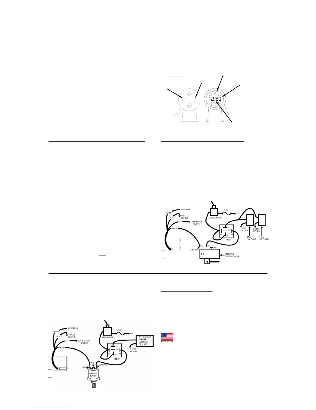
NOTE: When scrolling above 9990 RPM, a decimal point will appear in
the center of the display to indicate that the far right digit will not be
displayed (refer to figure 2).
5. Once the desired RPM is displayed, press the
SELECT
button to
return to the
MAIN MENU
.
6. Scroll to the HI parameter using the
SCROLL
button, and then press
the
SELECT
button.
7. Set the desired upper RPM threshold by following the above
procedure.
NOTE: The lower RPM limit of the HI parameter is the L0 set point.
8. Press the
SELECT
button to return to the
MAIN MENU
.
9. To exit programming mode, do not press any buttons for 5 seconds.
All changes will automatically store
and the unit will return to normal
operation.
9
NITROUS OXIDE SYSTEM CONTROL WIRING:
¾ The switched output is very useful for controlling Nitrous Oxide
activation/deactivation. Set the programmable L0 value to the
desired engine RPM where the device activates and the HI value to
the desired RPM where the device to deactivate (usually just before
the engine rev limiter triggers to prevent catastrophic engine
damage).
¾ Wire the Nitrous Oxide System, as illustrated below, using the
supplied relay and the
“Arming”
and
“Wide-Open-Throttle”
switch supplied with the Nitrous Oxide System.
¾ The
“Arming”
switch will deactivate the system so it can’t be
activated unexpectedly. The
“Wide-Open-Throttle”
switch will
only allow activation when the throttle is wide open, so the system
will shut down during shifts or deceleration, even if the engine RPM
is still in the activation range.
10
INTERCOOLER SPRAYER CONTROL WIRING:
¾ The RPM switched output, when used in conjunction with a pressure
switch is very efficient at controlling an intercooler CO2 or water
sprayer system during high boost and high engine RPM when the
efficiency of the intercooler falls off. This set-up works well to
conserve the CO2 or water supply for when it’s needed most.
¾ The pressure switch is used to activate the system only when the
boost pressure is high.
¾ The RPM switch is used to control the RPM at which the system is
activated so the system does not activate at low RPM when the
intercooler can easily cool the lower airflow.
11
CLEANING DIRECTIONS:
For proper cleaning of instrumentation/accessories, use a glass
cleaner or mild detergent with a spray on and wipe method.
WARRANTY INFORMATION:
TWO (2) YEAR LIMITED WARRANTY. SWP products are warranted
against defects in workmanship and materials for a period of two (2)
years from the date of purchase. Proof-of-purchase is required;
otherwise, the warranty period shall default to two (2) years from date-
of-manufacture (as indicated by the date code on the product). See
detailed Warranty Policy for other Terms & Conditions.
STEWART WARNER PERFORMANCE
1-866-SWP-RACE (797-7223)
www.SW-Performance.com
12
REAR VIEW FRONT VIEW
SCROLL
BUTTO
 Loading...