< 36 >
3) Secure the DISPLAY CONSOLE using five M512mm SCREWS(10) as shown.
4) Position the REAR COVER(11) at the back of the DISPLAY CONSOLE and secure it using four M510mm
TAPPING SCREWS(12).
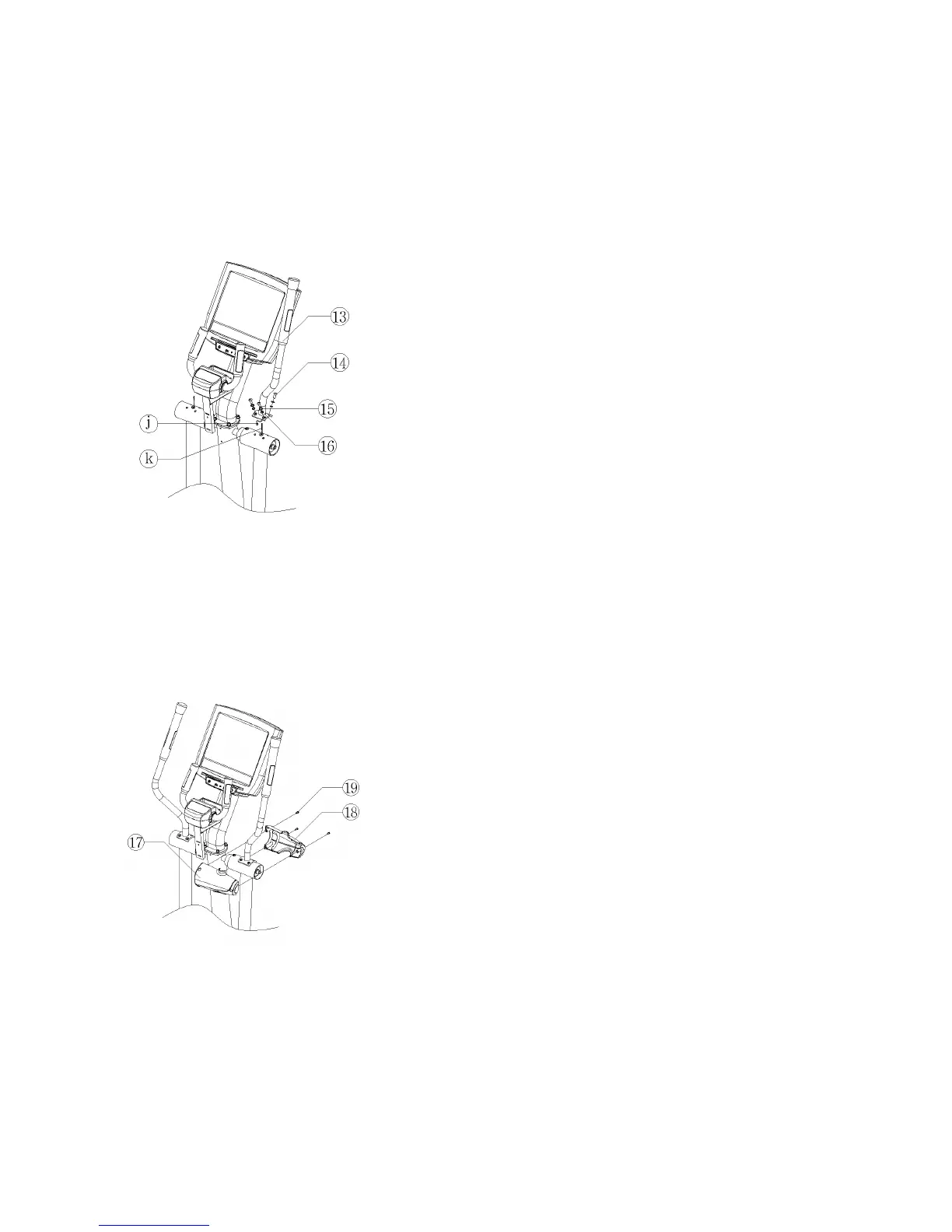
7. Secure the RIGHT ROTATING HANDLEBAR(13).
1) Position the RIGHT ROTATING HANDLEBAR(13) as shown.
2) Connect the HEART RATE CABLE(j) leading from the RIGHT
ROTATING HANDLEBAR to the CONNECTOR(k) extending from
the top of the right pivot arm.
3) Carefully slide the excess HEART RATE CABLE into the bottom of
the RIGHT ROTATING HANDLEBAR.
4) Align the mounting holes of the RIGHT ROTATING HANDLEBAR
with the mounting holes at the top of the right pivot arm. Secure them
together using four M815mm SCREWS(14), four M8 SPRING
WASHERS(15) and four O-RINGS(16).
Note: Be careful not to pinch the HEART RATE CABLE when
securing the RIGHT ROTATING HANDLEBAR.
8. Secure the LEFT ROTATING HANDLEBAR.
1) Repeat the step “7” to install the LEFT ROTATING HANDLEBAR.
9. Secure the SHOLDER LINK TOP COVERS.
1) Position the SHOULDER LINK TOP COVER_BACK(17) as shown.
2) Position the SHOULDER LINK TOP COVER_FRONT(18) as
shown.
3) Secure the SHOULDER LINK TOP COVERS using three
M512mm SCREWS(19).
4) Repeat the step “1) ~ 3)” to secure the other side SHOULDER LINK
TOP COVERS.