EasyManua.ls Logo

STI Stopper II - User Manual

STI Stopper II
5 pages
Print Icon
To Next Page IconTo Next Page
Loading...
Stopper
®
II Heated Enclosure
STI-1200A-HTR
STI-1200A-HTR240
INSTALLATION INSTRUCTIONS
Features:
Maintains initiating device temperature with external temperatures to -70°F (-57°C).
Independently tested to -102°F (-73°C).
Protects initiating devices for addressable units to UL 38 Standards.
The clear, protective polycarbonate cover is UV-stabilized against discoloration.
Enclosure rated to NEMA 3R Standards to provide a degree of protection against rain,
sleet, and damage from external ice formation.
Fan runs continuously to maintain a uniform temperature inside the enclosure.
Heater units cycle as required to maintain the correct range of operating
temperatures.
Polycarbonate backed by a lifetime warranty against breakage in normal use, one
year on electrical parts.
UL/ULC Listing does not require standby or secondary power for 110 or 240 VAC
50/60 Hz heater.
We Protect The Things That Protect You.
Safety Technology International, Inc.
ADA
Compliant
Question and Answer IconNeed help?

Do you have a question about the STI Stopper II and is the answer not in the manual?

Summary

Safety Warnings and Installation Notes

Enclosure Cleaning Instructions

Instructions for cleaning the polycarbonate enclosure using soap and water.

Product Specifications

Technical details including material, ratings, warranty, and performance of the enclosure.

Installation Guide

Mounting the Enclosure Backbox

Steps for mounting the enclosure backbox to the wall using provided hardware and anchors.

Install Pull Station and Monitor Module

Instructions for attaching the pull station and dual monitor module to the enclosure's slide plate.

Wiring Connections

Detailed wiring instructions for dual monitor module, fan, and high voltage AC supply.

Product Assembly Overview

Circuit Schematic Diagrams

Visual representation of high and low voltage circuits for the enclosure and its components.

Overview

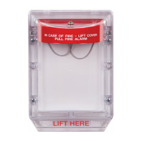
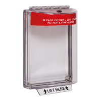
The Stopper® II Heated Enclosure, available as models STI-1200A-HTR and STI-1200A-HTR240, is designed to protect initiating devices, such as fire alarm pull stations, in extreme cold environments. It ensures that these devices remain operational and within specified temperature ranges, even when external temperatures drop significantly.

Function Description:

The primary function of the Stopper® II Heated Enclosure is to maintain the internal temperature of an initiating device, such as a fire alarm pull station, within an optimal operating range. This is achieved through an integrated heating system and a continuously running fan that circulates warm air. The enclosure is designed to protect the device from harsh environmental conditions, including extreme cold, rain, sleet, and external ice formation, while also preventing unauthorized access or accidental activation. It incorporates a clear, protective polycarbonate cover that is UV-stabilized to resist discoloration, ensuring visibility of the enclosed device. The system includes a low-temperature warning monitor and a high-voltage heater circuit, both supervised to ensure reliable operation.

Important Technical Specifications:

Polycarbonate Enclosure:

  • Flammability: UL94 V-2
  • Wall Thickness:
    • Backbox: 0.20 inches (5.1mm)
    • Cover: 0.12 inches (3.1mm)
  • NEMA Rating: 3R (provides protection against rain, sleet, and damage from external ice formation)
  • Warranty: Lifetime against breakage in normal use.

Silicone Laminate Heater:

  • Models:
    • STI-1200A-HTR: 110 VAC 50/60 Hz
    • STI-1200A-HTR240: 240 VAC 50/60 Hz
  • Power: 100 Watts
  • UL Recognition: UL Recognized Component
  • Life: @ -10°C (14°F) ~ 70°C (158°F) - 5 Years
  • Duty Cycle (Heater Cycling):
    • -40°F (-40°C): 16%
    • -70°F (-57°C): 38%
    • -99°F (-73°C): 100%
  • Power Requirement: Does not require standby or secondary power for 110 or 240 VAC 50/60 Hz heater, as the enclosure environment is supervised by a latching supervisory circuit in the alarm control unit or panel.

Fan:

  • Voltage/Current: 24 VDC (±10%), 90 mA
  • UL Recognition: UL Recognized Component
  • Life: 5 Years Continuous Duty
  • Operation: Runs continuously to maintain uniform temperature. Polarity sensitive (red lead positive).
  • Power Requirement: Requires a continuous 24 VDC supply.

Gasket:

  • Material: Neoprene
  • Life: 5 Years

Temperature Range:

  • Maintains initiating device temperature with external temperatures to -70°F (-57°C).
  • Independently tested to -102°F (-73°C).
  • Low temperature monitoring thermostat makes circuit at +32°F (0°C) and clears circuit at +50°F (+10°C).
  • Overtemp safety switch opens at 120°F (40°C) and closes at 80°F (27°C).
  • Heater control opens at 65°F (18°C) and closes at 40°F (4°C).

Electrical Connections:

  • High voltage (110 or 240 VAC) wiring enters through bottom conduit.
  • Low voltage and signaling wires enter through top conduit.
  • Wiring must remain separated per NFPA 70, NEC, and local codes.
  • All field wiring within the enclosure must be rated for a minimum operating range of 0°C - 110°C.
  • Requires three power sources: 110 or 240 VAC for the heater, 24 VDC for the circulating fan, and the fire alarm initiating circuit/temperature warning monitor.

Usage Features:

  • Protection: Protects initiating devices for addressable units to UL 38 Standards.
  • Environmental Resilience: NEMA 3R rating ensures protection against rain, sleet, and external ice formation.
  • Visibility: Clear polycarbonate cover allows for easy visual inspection of the enclosed device.
  • Accessibility: ADA compliant for ease of use.
  • Installation: Designed for straightforward installation with provided mounting hardware. Requires an outdoor-rated initiating station.
  • Supervision: The enclosure environment is supervised by a latching supervisory circuit in the alarm control unit or panel, ensuring that any issues are promptly detected.
  • Thermal Circuit Breaker: Includes a thermal circuit breaker to protect the heater circuit. If tripped, the 110 or 240 VAC power to the primary side of the breaker remains energized, requiring disconnection of supply power for safety.
  • Sun Shield Recommendation: For arid summer conditions, installing a dark-colored sun shield with sides is recommended to provide shade and promote upward airflow, helping to maintain the enclosure temperature closer to ambient.

Maintenance Features:

  • Cleaning:
    • Polycarbonate cover should be rinsed with water to remove abrasive dust and dirt, then washed with soap or mild detergent using a soft cloth. Rinse again and dry with a soft cloth or chamois.
    • Exercise caution when using water inside the enclosure; ensure the unit is completely dry before reassembling. Do not use razor blades.
    • For periodic testing or dusty conditions, cover return grill ports to minimize dust or sand entry. Accumulated dust can be removed using compressed air designed for electronic cleaning.
    • To clean the 24 VDC negative ground fan, disconnect all power and use electronic compressed air.
  • Component Replacement: Replacement of the heater assembly and gasket is required five years from the installation date. Contact STI for replacement Heater Kit STI-HK3.
  • Troubleshooting: If the thermal circuit breaker does not remain in a restored position, an electrical check of the various components is required. If the fan is not operating, check polarity and reverse the connections if necessary.
  • Installation Date Record: A label on the underside of the cover provides space to record the installation date for quick reference and maintenance scheduling.

STI Stopper II Specifications

General IconGeneral
BrandSTI
ModelStopper II
CategoryFire Alarms
LanguageEnglish

Related product manuals