47
b03
b02
b04
b04
b04
b04
b04
D0000019212
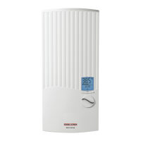
DEL SL
b02 Entry electrical cablesI
b03 Entry electrical cablesII
b04 Entry electrical cablesIII
c01 Cold water inlet Male thread G 1/2 A
c06 DHW outlet Male thread G 1/2 A
15.2 Wiring diagram
3/PE ~ 380-415 V
85�02�02�0005�
1 Heater
2 High limit safety cut-out
3 Safety pressure limiter
Priority control with load shedding relay (LR 1-A)
See also chapter "Appliance description/ Accessories".
85�02�02�0003�
2
1
1 Control cable to contactor of second appliance (e.g. electric
storage heater).
2 Control contact, opens when instantaneous water heater is
switched on.
15.3 DHW output
The DHW output is subject to the mains voltage, the connected
load of the appliance and the cold water inlet temperature.
The rated voltage and rated output can be found on the type plate
(see chapter "Troubleshooting").
Connected load in kW 38 °C DHW output in l/min.
Rated voltage Cold wateri nlet temperature
380 V 400 V 415 V 5°C 10°C 15°C 20°C
16,2 7,0 8,3 10,1 12,9
16,3 7,1 8,3 10,1 12,9
18,0 7,8 9,2 11,2 14,3
19,0 8,2 9,7 11,8 15,1
19,4 8,4 9,9 12,0 15,4
21,0 9,1 10,7 13,0 16,7
21,7 9,4 11,1 13,5 17,2
22,6 9,8 11,5 14,0 17,9
23,5 10,2 12,0 14,6 18,7
24,0 10,4 12,2 14,9 19,0
24,4 10,6 12,4 15,2 19,4
25,8 11,2 13,2 16,0 20,5
26,0 11,3 13,3 16,1 20,6
27,0 11,7 13,8 16,8 21,4
Connected load in kW 50 °C DHW output in l/min.
Rated voltage Cold wateri nlet temperature
380 V 400 V 415 V 5°C 10°C 15°C 20°C
16,2 5,1 5,8 6,6 7,7
16,3 5,2 5,8 6,7 7,8
18,0 5,7 6,4 7,3 8,6
19,0 6,0 6,8 7,8 9,0
19,4 6,2 6,9 7,9 9,2
21,0 6,7 7,5 8,6 10,0
21,7 6,9 7,8 8,9 10,3
22,6 7,2 8,1 9,2 10,8
23,5 7,5 8,4 9,6 11,2
24,0 7,6 8,6 9,8 11,4
24,4 7,7 8,7 10,0 11,6
25,8 8,2 9,2 10,5 12,3
26,0 8,3 9,3 10,6 12,4
27,0 8,6 9,6 11,0 12,9
 Loading...