16
2.2 Specification (The details listed on the type plate apply)
1)
(L20/F40/W35) = extract temperature 20 °C, extract air rel. humidity 40 %, heating flow temperature 35 °C
2)
(L20/F40) = extract air temperature 20 °C, extract air rel. humidity 40 %
Type
LWA 203 LWA 203 SOL LWA 303 LWA 303 SOL
Part no. 07 42 60
07 42 62 07 42 61 07 42 63
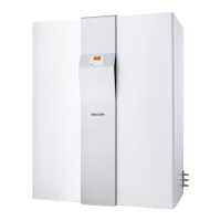
Dimensions H / W / D mm 1990 x 775 x 775
Weight dry/wet kg 187 / 490 212 / 498 190 / 493 215 / 501
Output details
Application range - extract air °C 15 - 30 15 - 30 15 - 30 15 - 30
Heating output HP at 250 m³/h/200 Pa and
(L20/F40/W35)1)
kW 1.5 1.5 2.1 2.1
Coefficient of performance HP to EN 255 part 2 (COP) 4 4 4 4
Coefficient of performance HP to EN 255 part 3 (COP(t)) 4.1 4.1 3.7 3.7
Heating output electric booster (heating) kW 6.6 6.6 6.6 6.6
Heating output electric booster (DHW) kW 1.5 1.5 1.5 1.5
Heating output HP (L20/F40/W35)1)+ electric booster kW 8.1 8.1 8.7 8.7
DHW heat-up time with HP from 15°C to 55 °C (L20/F40)
2)
h 10.1 9.0 7.3 6.5
Electrical specification
Max. power consumption kW 8.6 8.6 8.8 8.8
Max. power consumption A 17.5 17.5 18 18
Starting current (HP) A 10 10 13 13
Power consumption - fan at 250 m3/h / 200 Pa W 50 50 50 50
Power consumption - circulation pump W 46-93 46-93 46-93 46-93
Power supply electric booster + compressor (L1, L2, L3) n x mm
2
5 x 2.5 5 x 2.5 5 x 2.5 5 x 2.5
Mains transformer + control unit (L,N) n x mm
2
3 x 1.5 3 x 1.5 3 x 1.5 3 x 1.5
Fuse electric booster + compressor (L1, L2, L3) A 20 gl 20 gl 20 gl 20 gl
Fuse transformer, control unit, pump and fan (L, N) A 16 gl 16 gl 16 gl 16 gl
Voltage / Frequency - power unit V / Hz 3/N/PE ~ 400 / 50
Voltage / Frequency - control unit V / Hz 1/N/PE ~ 230 / 50
Protection EN 60529 (DIN VDE 0470) IP 20 IP 20 IP 20 IP 20
Heat pump
Permissible operating pressure, refrigeration circuit Mpa 2.34 2.34 2.34 2.34
Refrigerant Type R 134 a R 134 a R 134 a R 134 a
Fill level g 1000 1000 1000 1000
Central heating
Permissible operating pressure heating circuit MPa 0.3 0.3 0.3 0.3
Minimum heating volume flow l/h 400 400 400 400
Available pressure differential at the circulation pump at 400 l/h:
Speed stage 1
Speed stage 2
Speed stage 3
MPa
MPa
MPa
0.02
0.04
0.05
0.02
0.04
0.05
0.02
0.04
0.05
0.02
0.04
0.05
Temperature spread only for HP operation
400 l/h (L20/F40/W35)1)
K 3 3 4 4
Hot water
Permissible operating pressure DHW Mpa 0.6 0.6 0.6 0.6
Maximum DHW temperature via heat pump °C 60 60 60 60
Capacity DHW cylinder l 303 290 303 290
Ventilation
Extract volume flow for ventilation only m
3
/h 70 – 290 70 – 290 70 – 290 70 – 290
Minimum extract volume flow for HP operation m
3
/h 125 125 175 175
Max. available external pressure 250 m
3
/h air flow rate Pa 270 270 270 270
Max. permissible external pressure at nominal and minimum flow
rate
Pa 150 150 150 150
Connections
Heating connection mm Ø 22 (male) Ø 22 (male) Ø 22 (male) Ø 22 (male)
DHW connection Ø 22 (male) Ø 22 (male) Ø 22 (male) Ø 22 (male)
DHW circulation connection R ½" (male) R ½" (male) R ½" (male) R ½" (male)
Condensate connection mm Ø 22 female (hose 2 m long)
Water connection heat exchanger inch G 1 (male) G 1 (male)
Expelled air/extract air connections DN 160 160 160 160
Sound power level dB(A) 48 48 48 48

 Loading...


