2
Summary of LZM II functions
RS 232 interface for adjustment and
monitoring via a PC
System extension through the FE 7 remote
control
Input of the system and heat pump frost
protection limits
At least 24 h backup power for the clock
Automatic pump kick-start
Reset option
Stored fault list with precise fault code
indication, together with date and time
display
Rapid and accurate fault diagnostics using
system analysis including temperature
scan for heat pump and peripheral
equipment without requiring additional
equipment
Factory settings for time switch programs
for all heating and DHW circuits
1.2 Equipment description
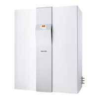
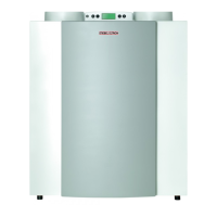
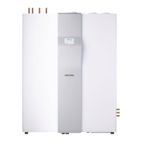
This device is a complete system with
heat recovery for central extraction and
decentralised ventilation, as well as for DHW
and central heating.
The air/water heat pump recovers waste heat
from the extracted air via a duct system. This
energy is channelled to the heating and/or
DHW system. The cooled air is expelled to
the outside. When the outside temperature is
very low, or when the heating requirement is
very high, the device covers the residual heat
demand of the system via an integral electric
booster heater.
Outside wall valves channel in fresh air; which
replaces air expelled by the heat pump.
The device is controlled by the weather-
compensated flow temperature controller LZM
II.
An additional push button (G) is built into the
plastic facia (Fig. 1). By activating this push
button, the electric booster heater heats the
DHW once to 65 °C in the upper third (or the
upper quarter for SOL versions) of the DHW
cylinder.
Special features of the SOL versions
These versions have an additional indirect coil
built into the DHW cylinder for DHW heating
with solar energy.
1.3 Operating and installation
instructions
Subject to the relevant system, also observe
the operating and installation instructions
of the components of which the system
comprises.
Keep these operating and installa-
tion instructions safely and pass them
on to any new user, should the equipment
change hands, and let your contractor check
their content in conjunction with any mainte-
nance and repair work.
1. Operating instructions for users and contractors
B
C
ED
F
A
6
7
8
9
10
1
2
3
4
5
11
1.1 Equipment summary
C26_03_01_0118
GH
A Display
B Rotary selector
C Rotary selector Reset / Auto
D Programming key
E Programming indicator
F Optical interface RS 232
G Immersion heater push button
H Safety pressure limiter control indicator
(see 1.9 "What to do if...?")
System status display
1 Mixer open
2 Mixer close
3 Circulation pump, heating circuit 2
"mixer circuit"
4 Circulation pump, heating circuit 1
5 Electric booster stages "heating"
6 Compressor
7 Ventilation
8 Defrosting
9 DHW heating
10 Solar circuit pump
11 Equipment menu

 Loading...


