7
3 Installation, connection and
sound emissions
3.1 Transport
To protect the equipment against damage,
it must be transported vertically inside its
packaging.
Short tipping to one of its longitudinal sides
is permissible. With the WPL....IK / IKS ensure
that the control fascia is at the top during
transport.
Lifting slings for handling the standard
machine can be hooked up anywhere on the
lower frame.
Protect the heat pump against severe impact.
3.2 Installation location
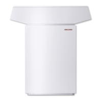
3.2.1 External installation (WPL....A / AS)
1. Undo the four screws from the non-
returnable pallet.
2. Remove the washers.
3. Remove the equipment from its pallet and
position it where required.
Recommended surfaces:
z Foundation (Fig. 5)
z Kerb stones (Fig. 6)
z Stone slab
Provide a recess (space) underneath the heat
pump to enable water and electrical pipes/
cables to be connected from below
(Fig. 5 and 9).
Ensure a minimum wall clearance on the air
outlet side of 2 m.
The heat pump must be accessible from all
sides. With external installations, water and
electrical pipes/cables can be routed into the
heat pump from below, i.e. through the knock-
outs in the floor of the refrigeration drive (Fig.
9).
Noise emissions for external installations
At the air inlet and air outlet sides, the heat
pump is louder than on the enclosed sides.
Therefore point these two sides away from
noise sensitive rooms of the house
(e.g. bedrooms).
The air inlet direction should be, where
practicable, in line with the main wind
direction, in other words, air should not be
drawn in against the wind.
Lawn areas and shrubs can contribute to the
reduction of noise. Noise can also be reduced
through dense palisades or similar.
Avoid installation on large echoing floor areas
(e.g. those covered with tiles) as well as in
between reflective building walls, both of
which could raise the sound level.
Ensure that noise cannot be emitted through
the floor plate of the heat pump or through
the installation aperture.
The machine emits 65 dB(A) (noise power
level) when installed externally.
Where the heat pump is installed on strip
foundations, seal off the open sides of the
foundation.
3.2.2 Internal installation
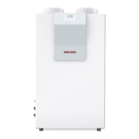
The WPL....I and WPL....IK heat pumps
are designed for internal installation,
except in wet areas.
1. Undo the four screws from the non-
returnable pallet..
2. Remove the washers.
3. Before removing the equipment from the
pallet, remove the equipment feet (1) in
Fig. 7 from the pack and insert fully into
the equipment.
4. Remove the equipment from its pallet and
position it where required. Use the sliding
shoes included in the pack to better
position the equipment (2).
5. Level the equipment by adjusting the
equipment feet.
The room in which the equipment is to be
installed must meet the following conditions:
z No risk from frost.
z Floor load-bearing strength (for the
equipment weight, see specification).
z Level, even and firm base.
z For a quiet heat pump operation on
floating screeds, remove the screed and
the anti-vibration insulation around the
installation location of the heat pump
(Fig. 8).
z The room must not be subject to a risk
of explosions arising from dust, gases or
vapours.
z The floor area of the installation room must
be at least 3 m², and the room must provide
a volume of 6 m³ (minimum).
z
When installing the heat pump in a
boiler room together with other heating
equipment ensure, that the operation
of other heating equipment will not be
impaired.
For internal installations, route the electrical
cables from the top into the heat pump
see item 4 in Fig. 10 and 11).
Cut out the inlets according to the cable Ø.
Noise emissions for internal installations
Never install the heat pump immediately
below or adjacent to living rooms or
bedrooms.
Never install the heat pump on timber floors
which form the ceiling below.
Recess floating screeds as shown
in (Fig. 8).
Make the heating flow and return connections
for the WPL....I using the flexible pressure
hoses supplied.
Anti-vibration mounts are already integrated
into the WPL....IK / IKS.
Protect all pipe fixings and wall transitions
with anti-vibration insulation.
Never direct the air inlet and outlet apertures
in external walls towards neighbouring
windows or living rooms/bedrooms.
The sound power level for internal
installations is:
inside the installation location 57 dB(A)
at the air inlet and outlet apertures 62 dB(A)
3.3 Heating water connection
3.3.1 The heat pump heating system must
be installed by a qualified contractor in
accordance with the water installation
drawings, which are part of the design
documents.
With regard to the safety equipment of
the heating system, observe DIN EN 12828
plus TRD 721 safety equipment [or local
regulations]. In dual-mode operation, the
return water of the second heat source can
flow through the heat pump. The return water
temperature may be a max. of 60 °C.
3.3.2 Protection of heating water pipes against
frost and moisture
(only for external installations)
Protect the flow and return pipes in external
installations against frost by means of
adequate thermal insulation, and by routing
them inside conduit against moisture (Fig. 9).
Maintain the required insulation thickness in
accordance with the Heating System Order [or
local regulations].The integral frost protection
control (inside the heat pump), which
automatically starts the circulation pump in
the heat pump circuit at + 8 °C and thereby
safeguards circulation in all water-bearing
components, offers additional frost protection.
The heat pump is started automatically no
later than when the temperature inside the
buffer cylinder drops below + 5 °C.
3.3.3 Flow and return connections
Connect the heating water side of the heat
pump in accordance with Fig. 9 (external
installation) or Fig. 10 and 11 (internal
installation). Check for leaks.
For internal installations, connect the anti-
vibration mounts supplied with the WPL 10 I.
Anti-vibration mounts are already integrated
into the WPL....IK / IKS.
Structure-borne noise is substantially
prevented by the anti-vibration construction
of the heat pump and by the flexible pressure
hoses, which act as anti-vibration mounts.

 Loading...


