10
3.7 Circulation pump
3.7.1 Circulation pump in the heat pump circuit
(buffer cylinder loading pump)
Determine the pressure drop for the intercon-
necting line between WPKI 5 and the heat
pump, if you are using the cylinders SBP 200
or SBP 700 (buffer cylinders) and the heat
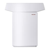
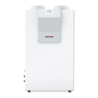
pump Compact Installation WPKI 5 (see table).
The total pressure drop is the sum of the pres-
sure drop for the interconnecting line, the heat
pump and the WPKI 5. Base the sizing of the
circulation pump on the nominal volume flow
and the total pressure drop.
Heat pump WPL 33
Nominal volume flow m³/h 1,4
Pressure drop
Heat pump hPa 190
SBP 700 + WPKI 5 hPa 55
Pressure hose 1¼“ hPa/m 4
3.8 Condensate drain
3.8.1 At the factory, a ¾“ hose is fitted to the
defrost pan as condensate drain hose, which
terminates near the knock-out on the floor
plate to the right of the refrigeration drive.
In case of external installation, route this hose
downwards out of equipment through the
aperture in base unit (Fig. 7). For internal in-
stallations route the defrost water into a public
sewer. The condensate hose can be routed to
the right, front or to the left out of the equip-
ment. For this, break out the knock-outs in the
side panel or in the floor plate of the refrigera-
tion drive and either at the front door or the
side panel (Fig. 8).
Ensure that the condensate drain hose is not
kinked anywhere over its entire length and is
routed with a slope.
Check after routing the hose that the con-
densate drains correctly. For this, slowly pour
approx. 10 l water into the defrost pan. The
water must completely drain out of the defrost
pan.
Use a condensate pump if there is insufficient
fall.
Install the heat pump approx. 100 mm higher,
if the condensate pump PK 9 (part no. see sec-
tion 1.6) is used for draining the condensate.
3.9 Buffer cylinder
A buffer cylinder is required to ensure trouble-
free heat pump operation. The buffer cylinder
(cylinder SBP) is not only installed as hydraulic
de-coupler for volume flow in the heat pump
circuit and the heating circuit, but primarily as
energy source for defrosting the evaporator.
3.10 Second heat source
For dual-mode systems, always connect the
heat pump into the return of the second heat
source (e.g. oil fired boiler).
3.11 Checking the fan
The fan must rotate in the correct direction.
Incorrect transport can slightly shift the fan,
resulting in the fan impeller dragging on the
inlet nozzle. If required, the fan retainer can
be moved to the left or to the right in its slots.
The height can be adjusted by a corresponding
rearrangement of the spacer brackets from the
top to the bottom of the retainer or vice-versa.
1
2
3
1 Spacer brackets, top
2 Spacer brackets, bottom
3 Fan
Drehrichtung
Fig. 10
Rotating
direction
C26_03_01_0662

 Loading...


