Edition Manual Chapter Page
2014-09-09 Workshop Manual, GGP Park 2 Chassis and body 5
10.Place a collecting tray under the pump for
collecting residual oil from the pump and
hoses.
Warning!
Do not spill any oil on the drive belts
during the disconnection of hoses
and tubes.
Warning!
Keep clean when handling hydraulic
parts. Dirt in the oil will cause
malfunctions and breakdowns.
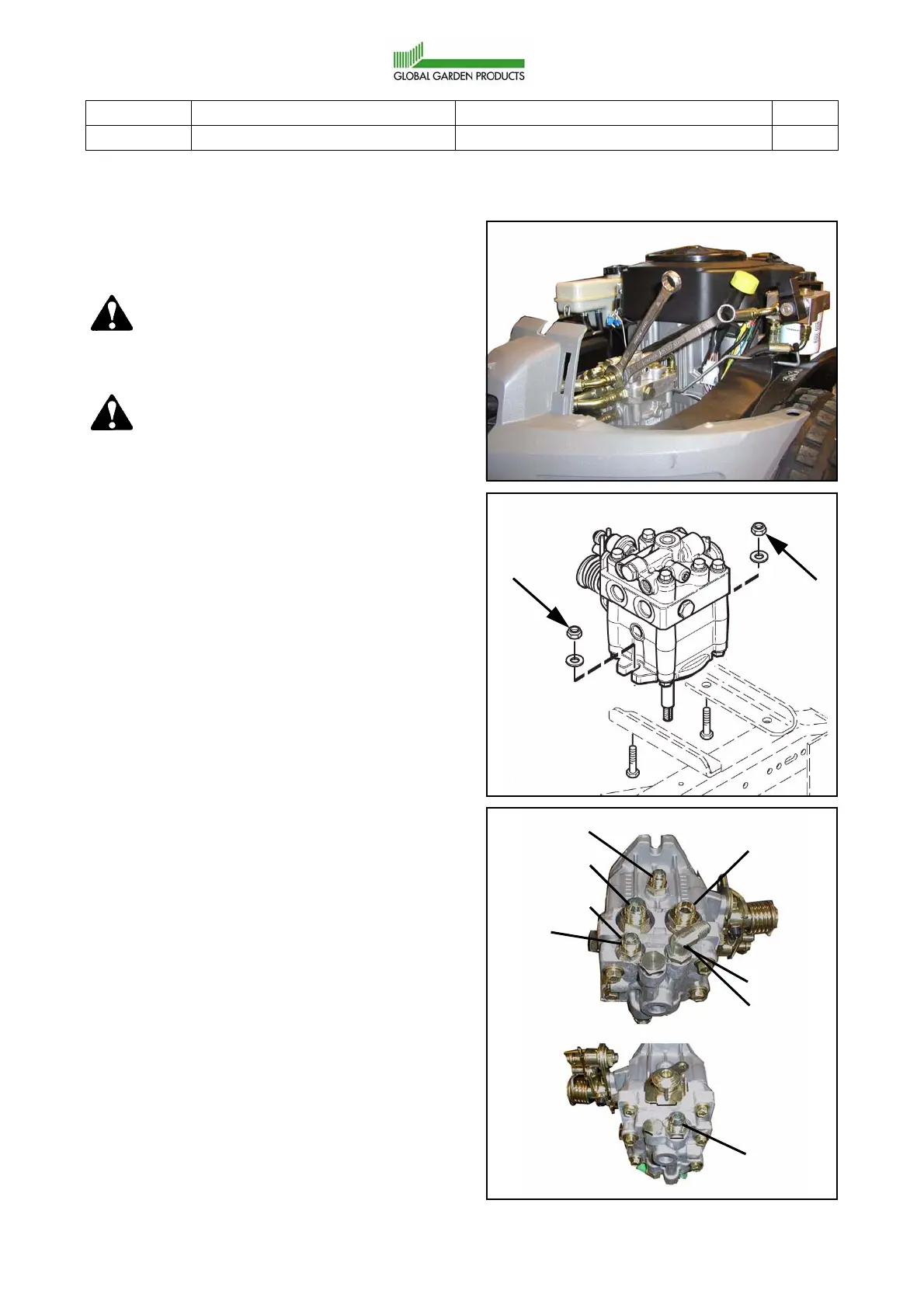
11.Disconnect all hoses and tubes from the
hydraulic pump. Always use two spanners,
one to hold the respective connection in the
pump and one to loosen the nut. See the
figure.
12.Remove the pump from the chassis by
unscrewing the two M10 mounting nuts and
screws. Use two 17 mm spanners. See the
figure.
13.Place and fasten the pump in a table vice.
Loosen the adapters from the pump.
14.Screw out the adapters and insert them in
the corresponding places in the new pump
one at a time. Check or replace the O-rings.
3. Place and fasten the new pump in a table
vice. Tighten the adapters to torques
according to the figures.
When tightening the angle adapter (A),
adjust it to 45° according to the horizontal
line. Use one 14 mm and one 19 mm
spanner.
If a metal tube shall be fitted to the adapters
A and B (machines without external
hydraulics), the connection nuts shall be
tightened with 41 Nm.
78 Nm
78 Nm
78 Nm
40 Nm
40 Nm
40 Nm
A
B
 Loading...