Edition Manual Chapter Page
2014-09-20 Workshop Manual, GGP Park 4 Hydraulic system 17
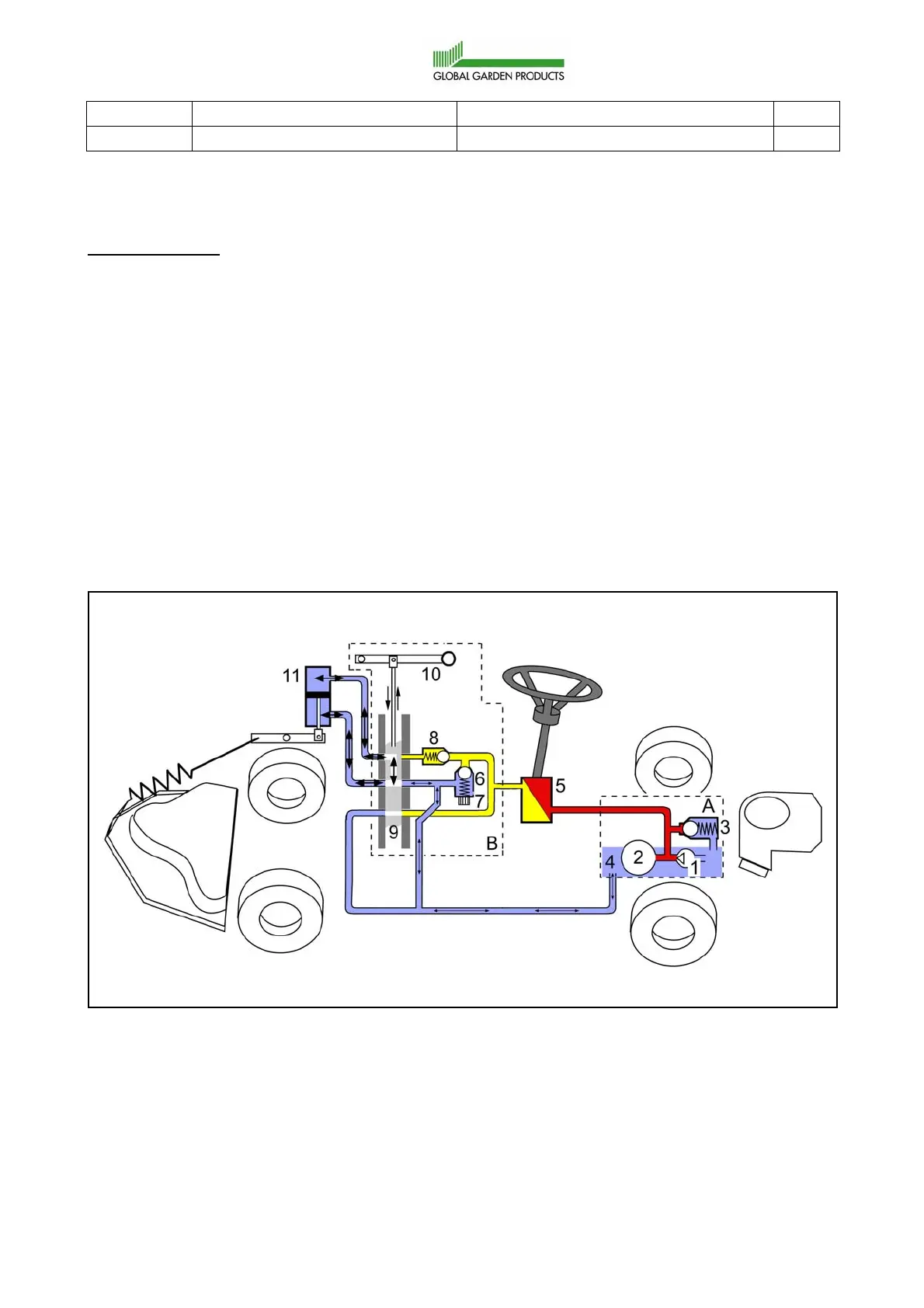
Floating position
Operation state:
• Motor is not running or is running in full speed.
• The steering wheel is actuated or not.
• The implement lifter is in its upper position.
The operator has actuated the hand lever (10), to its floating position (locked in front
position) which moves the slide (9) to change the hole pattern between the connections in
the valve. The hole pattern is adapted for the floating status. Both sides of the lifting cylinder
(11) is connected to each other and to the return line in the slide (9). I.e. no pressure can
reach any side of the cylinder. No oil pressure affects the cylinder. The main part of the oil
is flowing between the upper part and the lower part of the cylinder. A smaller part is flowing
between the oil container (4) and the cylinder due to the displacement of the piston rod. See
the arrows in the picture below.
In the floating position, the implement always rests against the ground with the same force
(the weight of the implement) and follows the contours of the ground.
 Loading...