Edition Manual Chapter Page
2014-09-23 Workshop Manual, GGP Park 7 Electrical System 2
7.1 Description
The electrical components are connected with cables, integrated in a complete insulated
harness, which is unique for each machine model. Thus the cables are protected against
wear, contaminations and other stresses. The cables are connected to the actual
components with tab or screw connectors and in some cases with multi-contact
connectors.
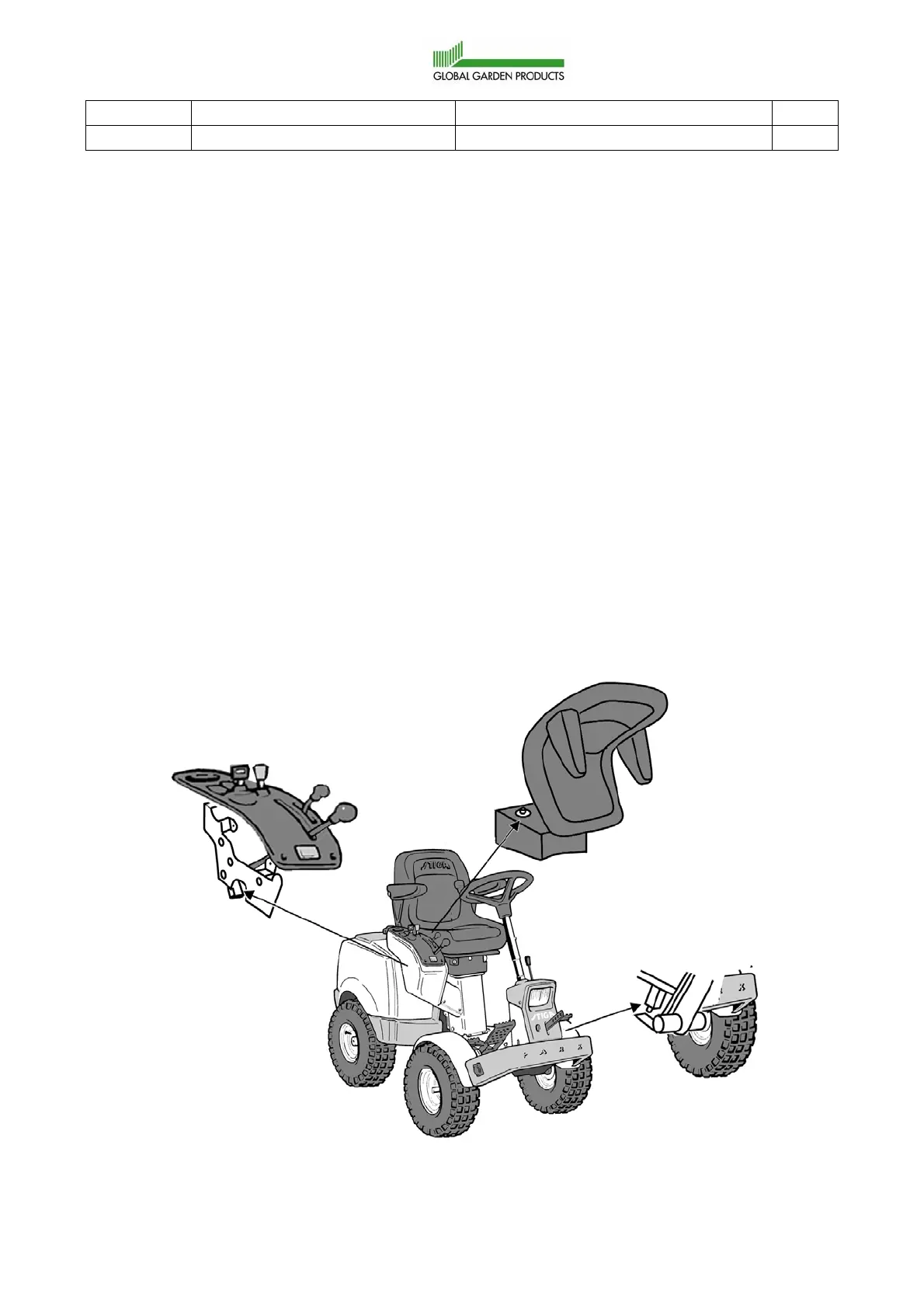
The electrical system contains several safety circuits. Therefore actual levers and pedals
are provided with micro switches. The micro switches are shown in the figure below. The
signals from the micro switches are used to interlock the actual circuit in case of a forbidden
manoeuvre attempt. Some manual switches and relays have also built in interlocks, related
to the safety system.
The wiring diagrams are presented separately in the respective spare parts manual. To
achieve a complete understanding of the electrical system for a certain machine, read also
the actual wiring diagram.
All current consumption circuits except the start circuit are protected by 1-3 fuses, de-
pending on the machine model.
Microswitch under the
Microswitch under the seat
Microswitch at the
control panel
brake pedal lever
 Loading...