5
tive gloves to handle the cutting devices.
Mount the components very carefully so as
not to impair the safety and efficiency of the
machine. If in doubt, contact your dealer.
WARNING! Unpacking and completing
the assembly should be done on a flat and
stable surface, with enough space for moving
the machine and its packaging, always mak-
ing use of suitable equipment.
-
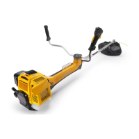
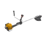
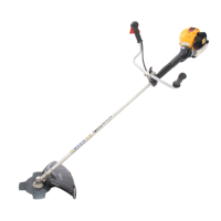
– Slide the contoured plate (1) until it is close to
the holes in the drive tube (2).
– Fit the top part (3) of the front handgrip on the
three holes provided on the drive tube (2) to
adjust the handgrip to the operator’s prefer-
ence.
-
(Fig. 2)
cap (2).
controls are on the right.
– Fasten the casing (4) of the controls to its ca-
ble fastener (5).
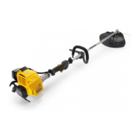
NOTE Loosening the knob (1) the handle bar can
be rotated to reduce its bulk for storage.
– Put the handle bar (5) into the seat in the sup-
the right.
– Fasten the casing (6) of the controls to its ca-
ble fastener (7).
NOTE Lifting the lever (1) the handle bar can be
moved to the position most comfortable for the
operator.
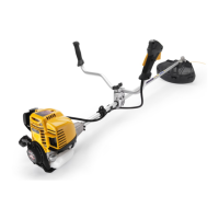
– Slide the contoured plate (1) until it is close to
the holes in the drive tube (2).
– Fit the top part (3) of the front handgrip on the
three holes provided on the drive tube (2) to
adjust the handgrip to the operator’s prefer-
ence.
– -
–
–
–
–
protruding hub of the front handgrip (14) and
–
on the support.
–
and (22) to the corresponding cables on the
DEVICE (Fig. 5)
WARNING! Each cutting device is pro-
vided with a specific guard. Never use guards
other than those indicated for each cutting
device.
WARNING! Wear protective gloves and
fit the blade guard.
– Insert the tab (3) in the guard seat (2) and fas-
DEVICES AND PREPARING GUARDS
WARNING! Use only original cut-
 Loading...