7.1.1 Reworking instructions
The assembly tools 5910 890 2220 supplied from
STIHL will in future already feature three additional
holes of diameter 5.5 mm (7/32") for use with TS 400.
An existing assembly tool which does not have
these holes can be reworked in accordance with the
template drawn to scale on the last page of this
Technical Information.
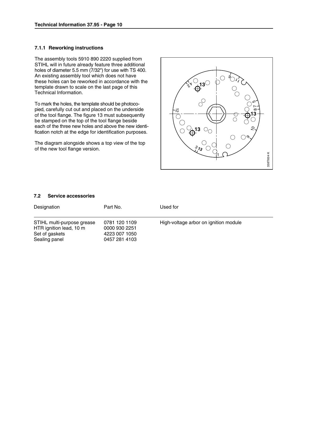
To mark the holes, the template should be photoco-
pied, carefully cut out and placed on the underside
of the tool flange. The figure 13 must subsequently
be stamped on the top of the tool flange beside
each of the three new holes and above the new identi-
fication notch at the edge for identification purposes.
The diagram alongside shows a top view of the top
of the new tool flange version.
7.2 Service accessories
Designation Part No. Used for
STIHL multi-purpose grease 0781 120 1109 High-voltage arbor on ignition module
HTR ignition lead, 10 m 0000 930 2251
Set of gaskets 4223 007 1050
Sealing panel 0457 281 4103
338TI004 K
13
2
3
4
5
6
7
8
9
10
11
12
1
13
13
13
Technical Information 37.95 - Page 10

 Loading...