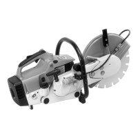
7. Special tools and service accessories
7.1 Special tools
Designation Part No. Use Comments
Assembly stand 5910 890 3100 Installation of the machine for repair
Locking strip 0000 893 5903 Locking the crankshaft 1)
Press sleeve 1127 893 2400 Pressing in the rotary shaft seal
Assembly sleeve 1122 893 4600 Protecting the rotary shaft seal on the
clutch side
Extractor 0000 890 4400 Extracting rotary shaft seals
- Jaws (No. 3.1 + 4) 0000 893 3706
- Jaws (No. 6) 0000 893 3711
Extractor 1116 893 0800 Extracting the flywheel
Insert, size 21 long 5910 893 5616 Releasing / tightening the clutch
Crimping tool 5910 890 8210 Fitting connectors to electric leads
Assembly pin 1108 893 4700 Assembly of the piston pin
Strap retainer 0000 893 2600 Tensioning the piston rings
Wooden assembly block 1108 893 4800 Positioning the piston
Carburetor and
crankcase tester 1106 850 2905 Leakage testing (crankcase and carburetor)
- Connector 0000 855 9200
- Fuel line 1110 141 8600
Vacuum pump 0000 850 3501 Leakage testing (crankcase)
Sealing plate 0000 855 8106 Sealing the exhaust outlet for leakage tests
Test flange 1128 850 4200 Leakage testing
Setting gauge 1111 890 6400 Setting the air gap between ignition
moduleand flywheel
Insert, size 13 5910 893 5608 Nut for flywheel
Insert, size 17 5910 893 5610 Nut for starter wheel
Torque wrench 5910 890 0301/02 Screw connections (0.5 to 18 Nm) 2)3)
Torque wrench 5910 890 0311/12 Screw connections (6 to 80 Nm) 2)3)
Insert, 1-5 x 120 x 6.3 0812 542 2104 Tightening the socket-head screws
with star-shaped recess
Assembly tool 10 5910 890 2210 Inserting the snap rings in the piston boss
Assembly hook 5910 890 2800 Disengaging the clutch springs
Assembly tool 0000 890 2201 Flaring the rope guide bush
Screwdriver with
tee-handle QI-5 x 150 5910 890 2400 For all hex socket-head screws
Pliers A10 0811 611 8200 Outer circlip on thrust washer
Pliers C19 0811 641 8380 Inner circlip on spindle bearing
and crankshaft
Drift pin 1119 893 7200 Pressing the needle sleeve into and out
of the V-belt pulley
Drift pin 4119 893 7200 Forcing out the deep groove ball bearings
in the spindle bearing
Assembly tool ZS 5910 890 2220 Removing the crankshaft 4)
- Screw sleeve 5910 893 2420 Installing the crankshaft
Comments
1) Important: Only this locking strip may be used to lock the crankshaft of the TS 400. The piston will be
damaged if one of the stop bolts in the set of STIHL special tools is used.
2) A torque wrench must be used to tighten DG screws
3) Versions 5910 890 0302 and 5910 890 0312 are fitted with an optical/acoustic warning device
4) Refer to the reworking instructions, Section 7.1.1
Technical Information 37.95 - Page 9

 Loading...