59TS 500i
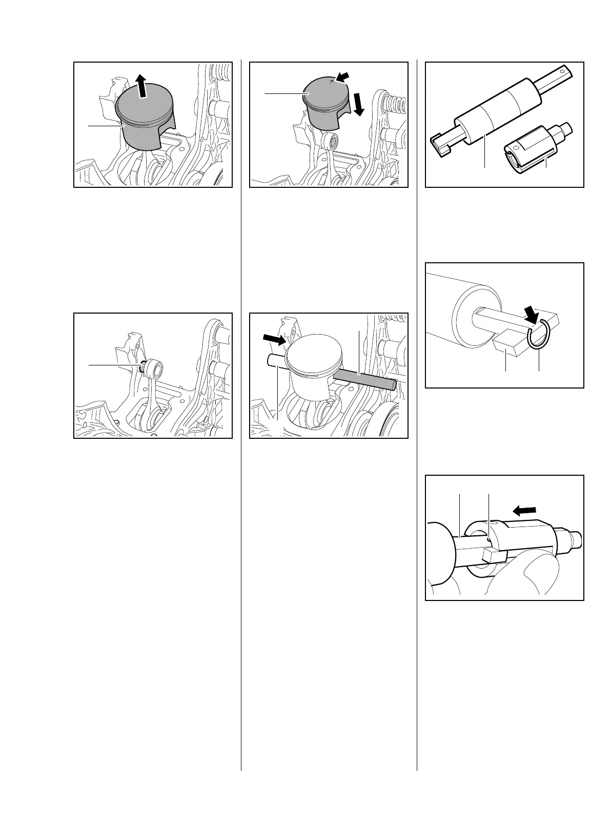
: Remove the piston (1) from the
connecting rod
– Examine the piston rings and
replace if necessary, b 6.9
Installation
: Take out the needle cage (1),
examine and clean it, replace if
necessary
: Coat the needle cage (1) with oil
and insert it in the rod eye
1307RA149 TG
1
1307RA357 TG
1
: Line up the piston (1) so that the
arrow (arrow) in the piston base
points towards the abrasive
wheel or cylinder exhaust port
: Position the piston (1) on the rod
eye
: Push assembly drift (1)
0000 893 4700 with the stub end
first through piston hole and rod
eye (needle cage) and secure the
piston
– Coat the piston pin with oil
: Fit the piston pin (2) on the stub
of the assembly drift (1) and slide
it into the piston
1307RA150 TG
1
1307RA140 TG
1
2
: Remove the sleeve (1)
5910 893 1706 from the
assembly tool (2) 5910 890 2212
: Attach the snap ring (1) to the
magnet (2) and align it so that the
snap ring gap is on the flat side
(arrow)
: Push the slotted diameter of the
sleeve over the magnet (2) and
snap ring
The inner pin (1) must point towards
the flat face of the tool's shank.
12
1307RA023 TG
1307RA029 TG
2 1

 Loading...