multaradar cd optimized inStallation
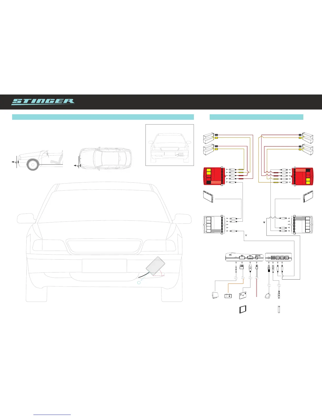
HD Antenne installation for MultaRadar CD
We advise to have the HD Antenna installed horizontally. However, those drivers who wish to have
optimized reception of MultaRadar CD signals can choose to have the antenna mounted diagonally,
as explained in the overview below.
2
45°
1. Diagonally place the antenna behind the bumper or
spoiler, with the smooth surface facing forward.
2. From the point of view of the driver, the cable connection must be on the
bottom right of the antenna.
Take note: If, from the point of view of the driver, the cable connection is on
the top right or bottom left, the reception will be strongly reduced.
90
o
Antenna must face outward
and parallel to the road
90
o
Aim antenna straight forward
 Loading...