Do you have a question about the STK Professional Audio V-16 Plus 4 and is the answer not in the manual?
Procedure for inspecting the product for physical damage after delivery and saving packing materials.
Details of the limited 2-year warranty, covering defects in materials and workmanship.
Instructions for filling out warranty information for personal records.
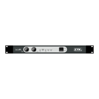
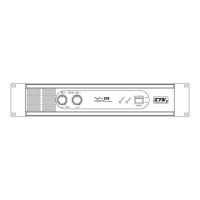
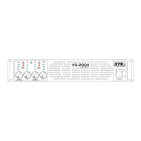
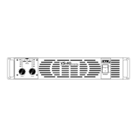
Description of controls and indicators on the front panel of the amplifier.
Description of connections and controls on the rear panel of the amplifier.
Guidelines for mounting the amplifier in a rack or on a flat surface, emphasizing ventilation.
Common-sense precautions for safe operation, including grounding, line voltage, and pre-connection checks.
Instructions for setting up and operating the amplifier in Quad mode for 4-ohm applications.
Instructions for bridging inputs and outputs for high-power stereo or mono operation, with 8-ohm minimum load.
Details on using Speakon connectors for speaker output, including pin configurations and connection tables.
How to connect speaker systems for stereo operation, specifying load impedance requirements.
How to connect speaker systems for bridged mono operation, specifying load impedance requirements.
Overview of the amplifier's input and output connections, detailing XLR and 1/4" jack compatibility.
Description of unbalanced 1/4" phone input jacks and their connection types.
Details on speaker output binding posts, safe connections, and polarity considerations.
Information on factory-set line voltage, required power cord, and fuse replacement guidelines.
Explanation of the Clip LED, indicating output distortion and how to manage it.
Explanation of the Mono/Bridge LED, indicating the selected operation mode.
Explanation of the Protect LED, indicating operational faults and troubleshooting steps.
Explanation of the Power Indicator LED, showing when the unit is powered on.
Diagram illustrating the hookup for a stereo PA system using the amplifier.
Diagram illustrating the hookup for a bi-amp PA system using the amplifier.
Diagram illustrating the hookup for a dual monitor system using the amplifier.
| Channels | 4 |
|---|---|
| Frequency Response | 20Hz - 20kHz ±0.5dB |
| Total Harmonic Distortion | <0.05% |
| Input Sensitivity | 0.775V |
| Damping Factor | >200 |