BEFORE YOU INVERT make sure that the inversion table rotates
smoothly to the fully inverted position and back, and that all fasteners are secure.
Make sure the user settings described below are properly adjusted for your unique
needs and body type. Take your time nding your proper settings and remember
them. Check these settings every time prior to using the equipment.
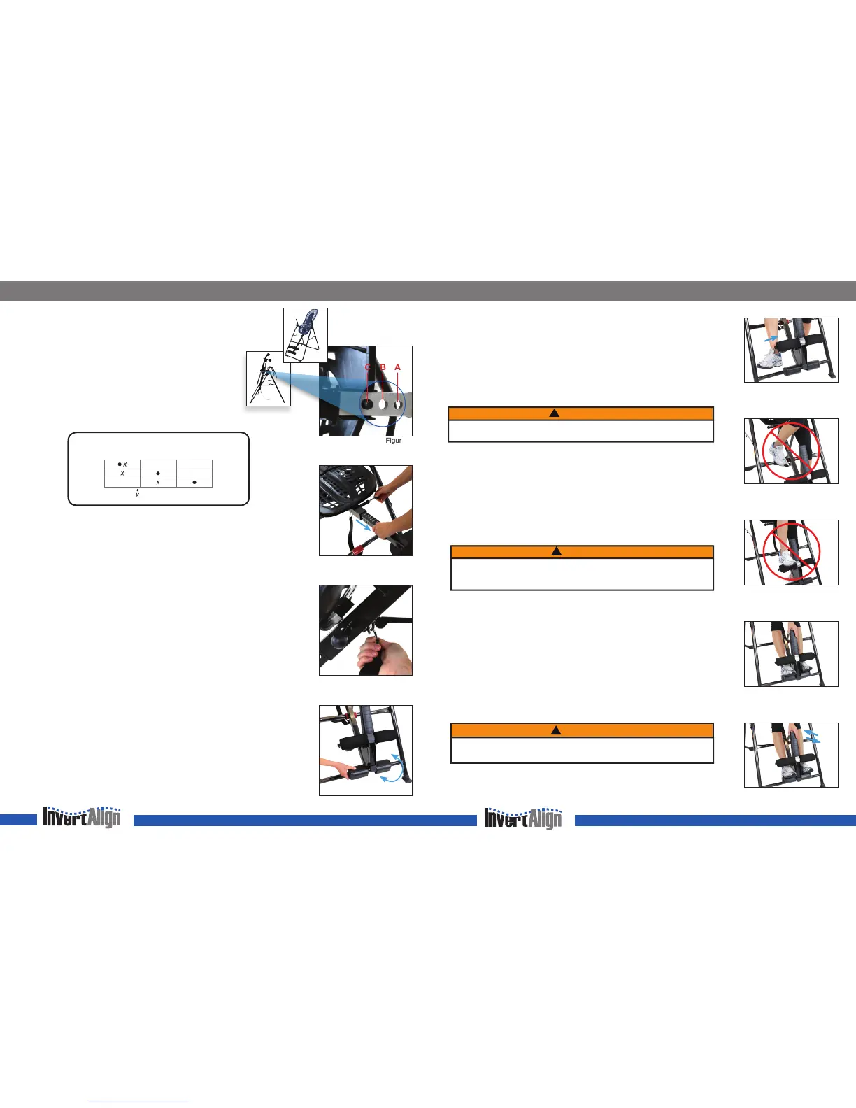
Roller Hinges: Find Your Setting
The Roller Hinges control the responsiveness or rate of rotation. There
are three holes; the hole selection depends both on your body weight
and the rotational responsiveness you desire (diagram below). For
users just learning to use the inversion table, we recommend starting
with Setting C (Figure 1).
IMPORTANT: Set the Roller Hinges in the same hole setting on each side.
Height Setting: Adjust the Main Shaft
The height settings are labeled on the Main Shaft in both inches and centimeters.
• Pull out the Height-Selector Locking Pin with your right hand while sliding the
Main Shaft with your left (Figure 2).
• Slide the Main Shaft until the last setting you can read is one inch greater than your
height. e.g. if you’re 5’10” (178 cm) the last numbers you’ll be able to read will
be 5’11” (180 cm).
NOTE: The best height setting for you will depend on your weight distribution and
could vary one or two inches on either side of your actual height. Starting at one or two
inches more than your height will help to ensure that the rotation of the table is not too fast.
• Release the Height-Selector Locking Pin so that it fully engages in a hole.
Angle Tether: Adjust to Desired Angle
For rst time users, attach the Angle Tether to help control your angle of rotation (Figure 3).
You can increase the angle of rotation allowed by the Angle Tether as you become more
comfortable using the table, or remove it for full inversion.
Ankle Comfort Dial: Find Your Setting
The Ankle Comfort Dial can rotate into a High or Low setting (Figure 4). There is a one inch
height difference between the settings. The setting you select will vary by the type of shoes
you wear and your ankle type. Try inverting in both settings to determine which one is most
comfortable for you.
The Ankle Comfort Dial should be set so the Foam Rollers and Heel Cups are secure
around the smallest part of the ankles (with minimal distance between the Ankle Lock
System and the top of your foot); this will reduce sliding on the Table Bed while inverted.
Prepare to Mount
•
ALWAYS
wear securely tied, lace up shoes with a at sole, such as a tennis shoe.
• DO NOT wear shoes with thick soles, boots, high-tops or any shoe that extends above
the ankle bone, as this type of footwear could interfere with properly securing your ankles.
FIND YOUR SETTINGS
Figure 1
Figure 2
Figure 4
Figure 3
SECURE YOUR ANKLES
Securing Your Ankles
• Stand with your back to the Table Bed—do not use the inversion table face-down.
• Step over the Main Shaft, placing your feet on the oor on either side. Press down and
push out on the ratchet to open the Ankle Lock System. To balance yourself, rest only
your lower body against the Table Bed as you slide one ankle at a time between the
Foam Rollers and the Heel Cups, placing your feet on the Ankle Comfort Dial.
• Be sure to slide your ankle in from the side (Figure 5); DO NOT insert your foot as
you would slide your foot into a shoe. Your feet should always be either on the oor
or on the Ankle Comfort Dial; never use any other part of the inversion table as a step
(Figures 6 and 7) .
• Press your ankles back rmly against the Heel Cups.
• Rotate the top of the Heel Cups toward your ankles to increase comfort while inverting.
• Push down on the handle of the Ankle Lock System, pull toward your legs and release
when the t is snug (Figure 8).
• Test the closure by jiggling the handle from front to back to make sure the foot clamps
are locked securely (Figure 9). Make sure your pant legs do not interfere with obtaining
a secure closure.
• Use the concept of HEAR, FEEL, SEE every time you secure your ankles: HEAR the
locking ratchet click into place; FEEL the locking ratchet to make sure it is fully engaged
in its setting; SEE that the ratchet is secure, and does not move out of position.
Test Your Balance Setting
The inversion table is sensitively balanced, and it responds to very small changes in weight
distribution. As a result, you must always test to make sure you have the correct height
setting. Ensure that there is clearance to rotate in front, above and behind you. To begin,
rest your head on the bed and slowly place your arms on your chest.
• If your head is lower than your feet, lengthen the height setting by one hole and
test again.
• If your feet do not move at all, shorten the height setting by one hole and test again.
• If the table comes to rest with your feet lifted a few inches off the A-frame, then you
have found the correct balance setting.
This is an important step—spend the time needed to nd your correct balance setting.
Your setting should remain the same as long as your weight does not uctuate substantially.
WARNING
!
DO NOT step on the crossbar of the A-frame or on top of the Ankle Lock System
as this could cause the table to rotate resulting in serious injury or death!
WARNING
!
DO NOT lean your upper body against the Table Bed before securing your ankles.
FAILURE to engage the Ankle Locking System fully could result in serious injury
or death! DO NOT deviate from these instructions.
WARNING
!
For your rst few inversion sessions, ask a spotter to assist you until you are able to
nd your correct balance setting and are comfortable with the operation of the table.
B AC
A B C
Top (closest to Pivot Pin)
Most Responsive Setting
Middle
Moderately Responsive
Bottom (furthest from Pivot Pin)
Least Responsive
80 - 120 lbs.
120 - 220 lbs.
(36 - 54 kg.)
220 - 300 lbs.
(54 - 100 kg.)
(100 - 136 kg.)
Beginner / Partial Inversion
Suggested for Full Inversion
Roller Hinge Selection Per User Weight
Figure 5
Figure 8
Figure 7
Figure 6
Figure 9
Ready for use
Bed rotated for adjusting
the Roller Hinge Setting
 Loading...