USER MANUAL
WWW.STRANDLIGHTING.COM
VISION.NET HARDWARE
13
4
VISION.NET DIN RAIL
RACK TRAYS
1
VISION.NET DIN RAIL
RACK MOUNT TRAYS
443581626886
OVERVIEW
PRODUCT NAME ORDER CODE
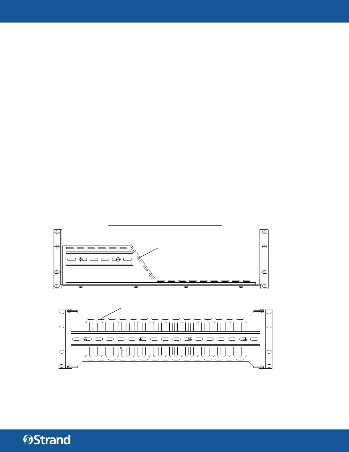
Vision.Net DIN Rail Rack Mount Tray, Horizontal (3U) 53906-101
INSTALLATION
To install Vision.Net DIN Rail Rack Mount Trays:
Step 1. Unpack rack tray. Rack trays include cage nuts and 10-32 screws for mounting the tray and blanking
cover. If your rack rails are pre-drilled validate the required screw size. Test fi t the position of tray in
rack to determine the desired mounting location. Both trays utilize 3U of space.
Step 2. Insert cage nuts (if required) into rack rail at required locations. The holes on the top and bottom of
the tray will support the tray itself and the middle holes are for mounting the blanking cover.
Step 3. Align tray into rack and insert four screws while supporting tray from below. Do not over-tighten
screws as damage may occur to rack rails or cage nuts may become stripped.
Step 4. Run all required wiring, following standard safety procedures as well as the requirements for your
DIN rail components being installed. Secure wiring as required using nylon cable ties to the pre-
drilled holes in the tray.
Step 5. Install blanking cover using 4 screws.
2
VISION.NET DIN RAIL
RACK MOUNT TRAYS
443581626886
WARNINGS AND NOTICES
When using electrical equipment, basic safety precautions should always be followed including the following:
• For indoor, dry locations use only. Do not use outdoors.
• Do not mount near gas or electric heaters.
• Equipment should be mounted in locations and at heights where it will not readily be subjected to
tampering by unauthorized personnel.
• The use of accessory equipment not recommended by the manufacturer may cause an unsafe condition
and void warranty.
• Not for residential use. Do not use this equipment for other than intended use.
©2022 Signify Holding. All rights reserved.
All trademarks are owned by Signify Holding or their respective owners. The
information provided herein is subject to change, without notice. Signify does
not give any representation or warranty as to the accuracy or completeness of
the information included herein and shall not be liable for any action in reliance
thereon. The information presented in this document is not intended as any
commercial o er and does not form part of any quotation or contract, unless
otherwise agreed by Signify. Data subject to change.
CUSTOMER SERVICE
If you have any questions regarding this product,
please contact Customer Service by phone at
+1 214-647-7880 or by email at entertainment.
service@signify.com.
WARNING: Observe maximum load rating for each tray.
Horizontal Tray: 30 lb. (13.6 kg)
Vertical Tray: 15 lb. (6.8 kg)
cable tie cutouts
cable tie cutouts
 Loading...